KY8030 Programmers Manual.pdf - 第36页
34 | KY-8030 Series (KYOS-2007001_rev0) 3D In ‐ line Solder Paste Inspection Systems 1.3.3. Edi t 1) Add Pattern Register one or more flas h or trace in a pattern. The “Add Pattern” Dialog Box View The pict…
Programmers Manual
| 33
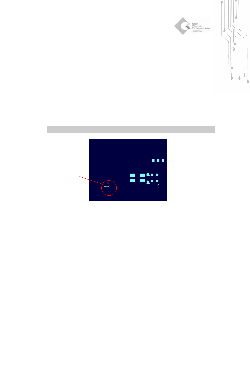
4) Point
Change the mouse pointer mode to Point Selection mode.
You can select any point to perform the following tasks:
1) To set the origin : Choose "Setup ▶ Origin" in the menu bar.
2) To calculate a position : Choose "View ▶ Position" in the menu bar.
You can select or unselect a point as follows:
1) To select a point: Click your mouse over a point.
2) To unselect a point: Choose "Select ▶ Unselect" in the menu bar.
Ú Caution: When calculating a position with a point, a positional deviation may occur.
5) Unselect (Esc)
Unselect all selected items (flash, trace, pad or point).
A Selected Point
34 | KY-8030 Series(KYOS-2007001_rev0)
3DIn‐lineSolderPasteInspectionSystems
1.3.3. Edit
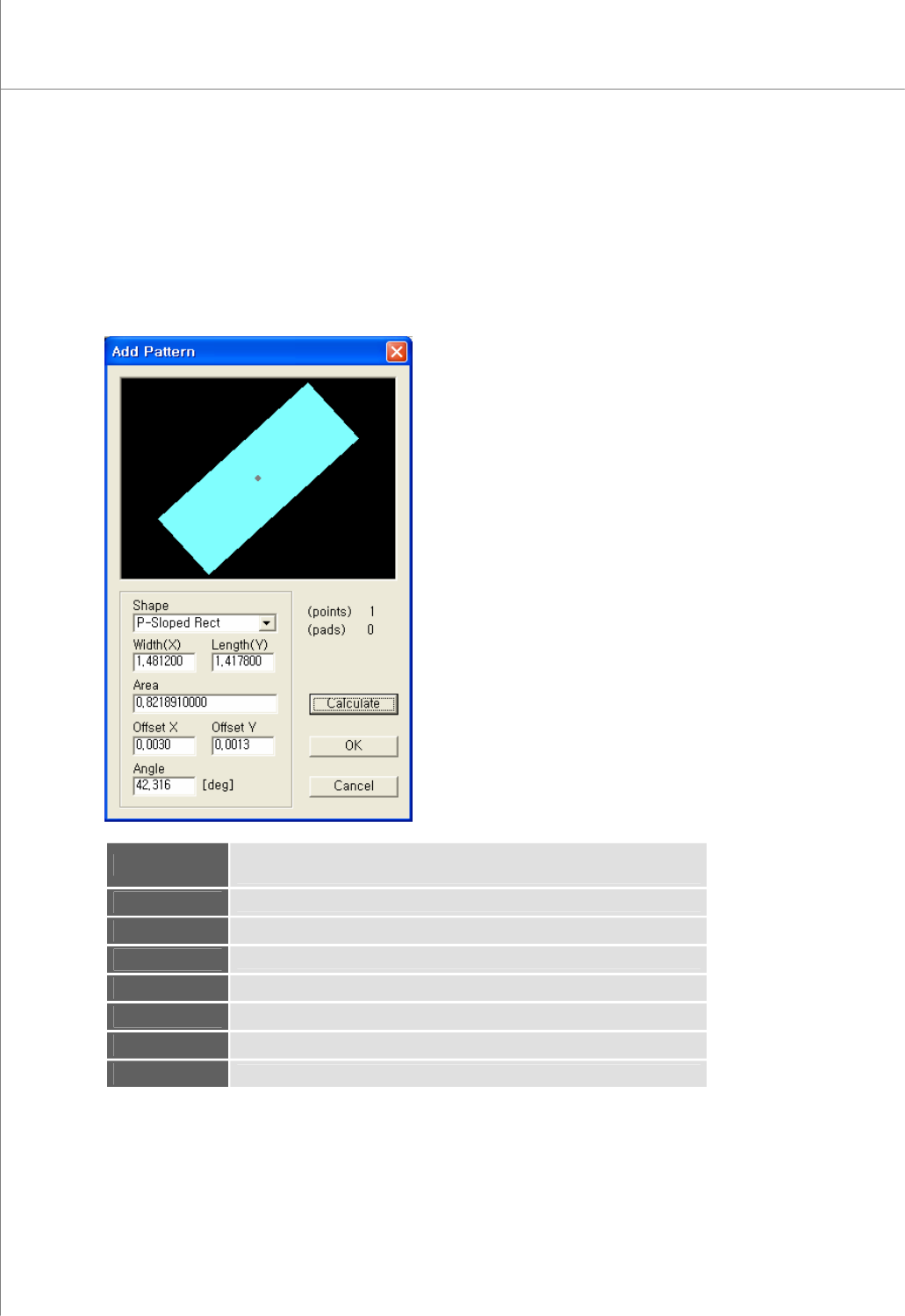
1) Add Pattern
Register one or more flash or trace in a pattern.
The “Add Pattern” Dialog Box
View
The picture of the currently selected pattern.
The gray point represents the center of gravity.
(points)
The number of flash(es) and trace(s) contained in the pattern
(pads)
The number of pads created with the pattern
Shape
The shape of the pattern
Width
The width of the pattern
Length
The length of the pattern
Area
The area of the pattern
Offset X
The Center of Gravity X - The Center of Area X
(View)
Programmers Manual
| 35
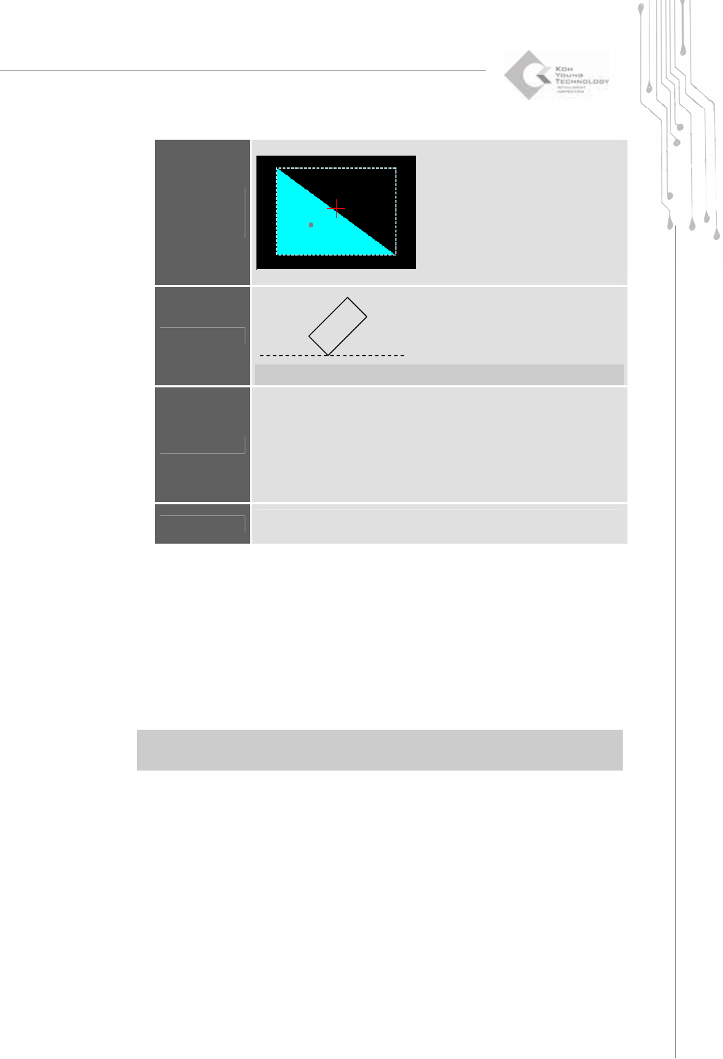
Offset Y
The Center of Gravity Y - The Center of Area Y
o : The Center of Gravity +: The Center of Area
Angle
P-Sloped Rect. : 1
θ
N-Sloped Rect. : 2
θ
−
Ú Note: This is used for the P-sloped or N-sloped rectangle shape only.
Calculate
Recalculate the area and offset values.
Depending on a shape, the area is calculated in different ways as follows:
E.g.) Rectangle = Width X Length
Circle = π X(0.5 * Width)
2
Others: Measured by video processing technique.
※ Caution: Make sure to select the correct shape. Otherwise, it may lead
to the wrong area value.
OK
All identical flashes and traces within a work area are found and registered
as pads automatically.
2) Modify Pattern
Modify pattern data for the selected pad.
The “Pattern” Dialog Box
For more information on how to modify a pattern, see the "Pattern" dialog box
under "4.1.7 Pad Bar" on page 41.
3) Remove Pattern (Shift + Del)
Remove all pads that are identical with the pattern for the selected pad.
※ Note: “Remove Pattern” lets you remove all pads that have the same pattern as the selected
pad while “Remove Pad” lets you remove only the selected pads.
4) Remove All Patterns
Remove all registered patterns.
1
θ
2
θ