KY8030 Programmers Manual.pdf - 第93页
Programmers Manual | 91 8) Edit PAD In the “Edit PAD” dialog box , enter pad information and click the OK b utton. The pad information will be ch anged. “Edit PAD” Dialog Box Pad ID Pad ID. Note: Upon pad creation , a …
90 | KY-8030 Series(KYOS-2007001_rev0)
3DIn‐lineSolderPasteInspectionSystems
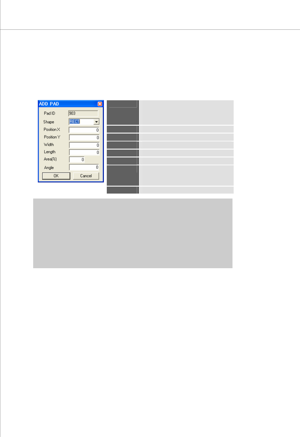
7) ADD PAD
In the “ADD PAD” dialog box, enter pad information and click the OK button. A new
pad will be created.
The “ADD PAD” Dialog Box
Pad ID
Pad ID.
Note: Upon pad creation, a pad ID is
automatically assigned and cannot
be changed.
Shape
The shape of the pad
PositionX
The X-coordinate of the pad
PositionY
The Y-coordinate of the pad.
Width
The width of the pad
Length
The length of the pad
Area(%)
The actual area of the pad.
Note: Click the CAL.button to calculate the
actual area of the pad shape.
Angle
The angle of the pad
※ Note: The available pad shapes are as follows:
R - Rectangle
C - Circle
D - Rounded Rectangle
O - Oblong
U - Undefined
P-Sloped Rectangle (pad sloped forward at 45°),
N-Sloped Rectangle (pad sloped backward at 45°),
Programmers Manual
| 91
8) Edit PAD
In the “Edit PAD” dialog box, enter pad information and click the OK button. The pad
information will be changed.
“Edit PAD” Dialog Box
Pad ID
Pad ID.
Note: Upon pad creation, a pad ID is
automatically assigned and
cannot be changed.
Shape
The shape of the pad
PositionX
The X-coordinate of the pad
PositionY
The Y-coordinate of the pad.
Width
The width of the pad
Length
The length of the pad
Area(%)
The actual area of the pad.
Note: Click the CAL.button to
calculate the actual area of the
pad shape.
Angle
The angle of the pad
Change Option
Note:
One PAD - Change the shape, size or
area of a single pad.
Selected - Change the shape, size or
area of the selected pads.
※ Note: The available pad shapes are as follows:
R - Rectangle
C - Circle
D - Rounded Rectangle
O - Oblong
U - Undefined
P - Sloped Rectangle (pad sloped forward at 45°),
N - Sloped Rectangle (pad sloped backward at 45°),
带格式的:
项
目符
号
和
编号
92 | KY-8030 Series(KYOS-2007001_rev0)
3DIn‐lineSolderPasteInspectionSystems
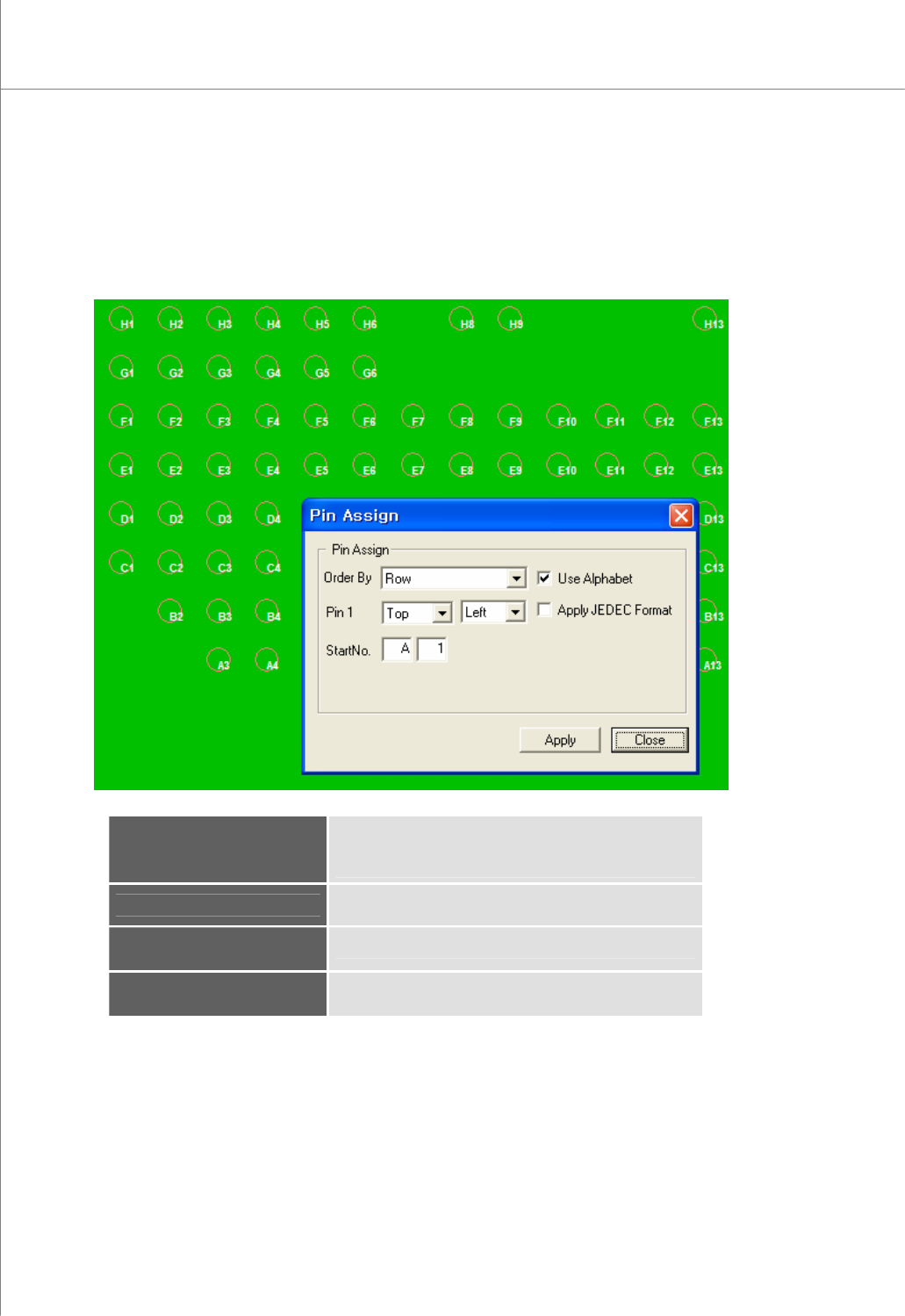
9) Manual Pin Assignment
In the “Pin Assign” dialog box, enter the required information and click the Apply
button. A pin number will be automatically assigned.
The “Pin Assign” Dialog Box
Order By
Specify the order in which pin numbers will be assigned.
(available options: Row, Column, Clockwise,
Counterclockwise)
Pin1
Select a start position.
Select : Top/Bottom Left/Right
Start No.
Start number (Alphabet + Number)
Apply JEDEC Format
Numbering with JEDEC format