KY8030 Programmers Manual.pdf - 第6页
4 | KY-8030 Series (KYOS-2007001_rev0) 3D In ‐ line Solder Paste Inspection Systems 2) Select Menu Flash * Select flash(es). Trace * Select trace(s). Pad * Select pad(s). Point Select a point. Unselect Cancel…
Programmers Manual
| 3
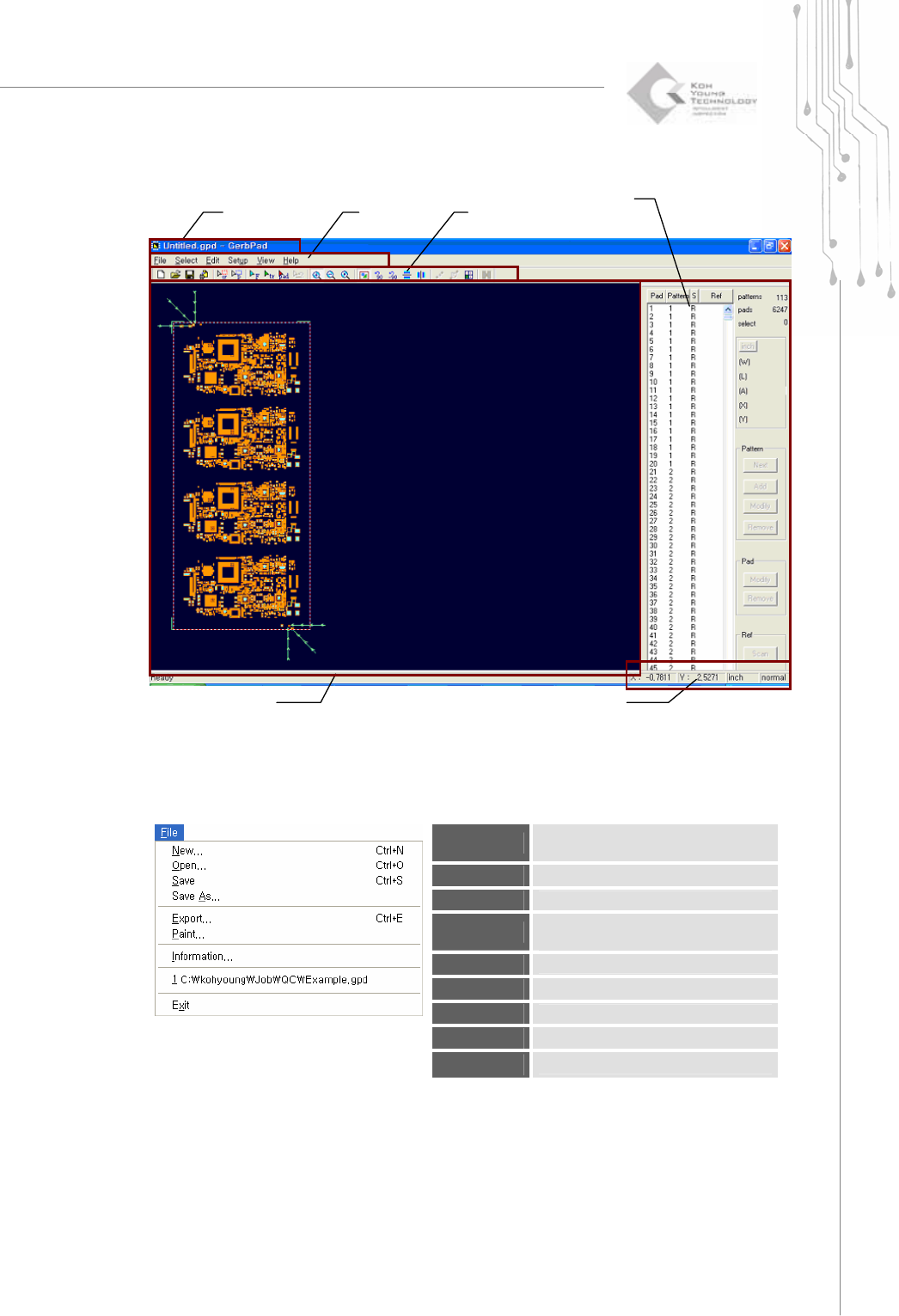
1.1.2. Screen Layout
1.1.3. Menu Layout
1) File Menu
New
Load a Gerber file to create a new
work file.
Open
Open a work file.(*.gpd )
Save
Save a work file. (*.gpd )
Save As
Save a work file under a different
name. (*.gpd )
Export
Create a pad file.(*.pad)
Paint
Export it as a bmp file.
Information
Show information on a work file.
Recent File
Open the most recent work file.
Exit
Exit the program.
Tool Ba
r
Status Display Bar
Pad Bar
Main view
Title Bar
M
e
n
u
4 | KY-8030 Series(KYOS-2007001_rev0)
3DIn‐lineSolderPasteInspectionSystems
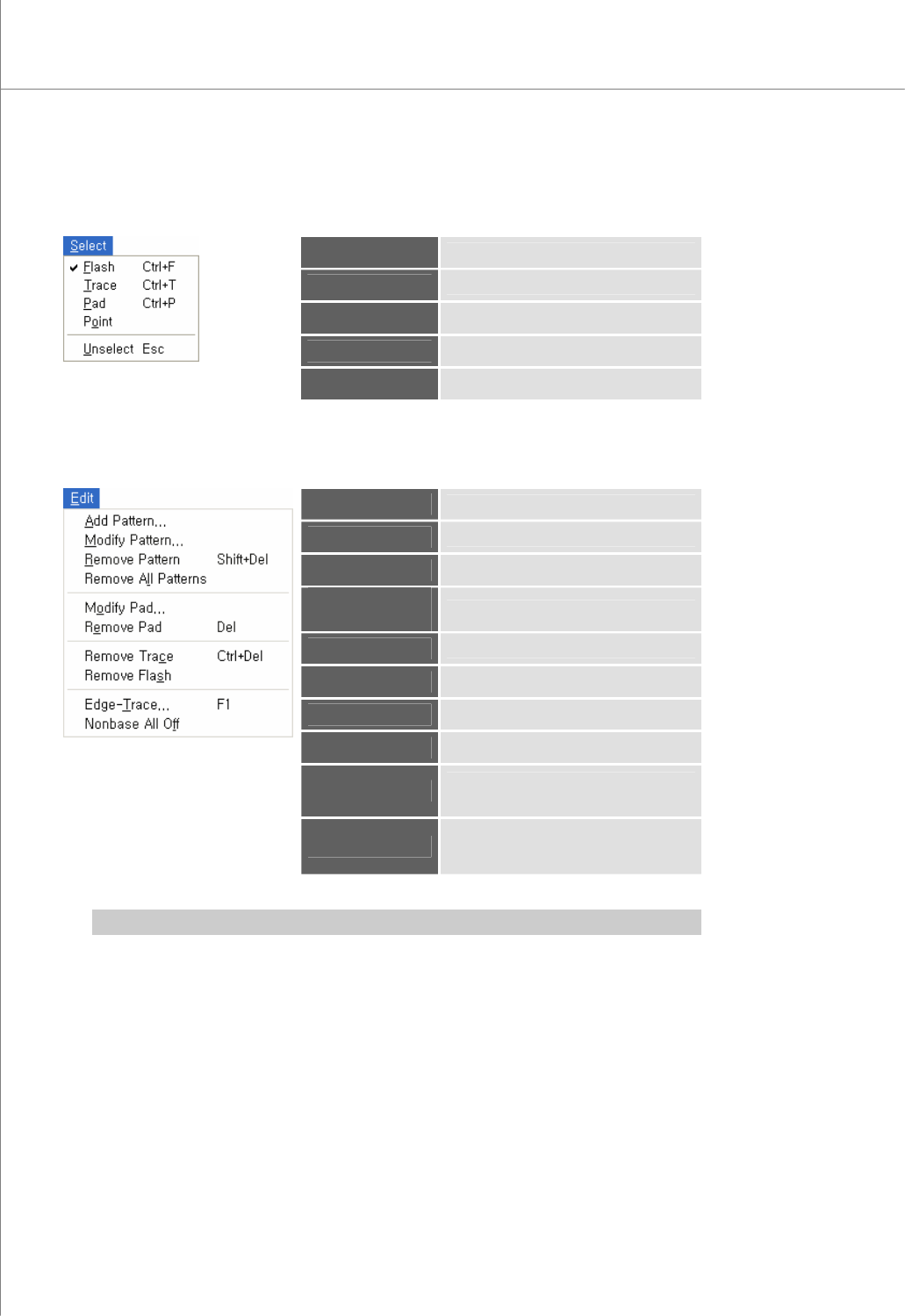
2) Select Menu
Flash
* Select flash(es).
Trace
* Select trace(s).
Pad
* Select pad(s).
Point
Select a point.
Unselect
Cancel a previous selection.
3) Edit Menu
Add Pattern
* Add a pattern.
Modify Pattern
Modify the selected pattern(s).
Remove Pattern
Remove the selected pattern(s).
Remove All
Patterns
Remove all patterns.
Modify Pad
Modify the selected pad(s).
Remove Pad
Remove the selected pad(s).
Remove Trace
Remove the selected trace(s).
Remove Flash
Remove the selected flash(es).
Edge-Trace
Retrieve the contour lines of flash(es)
and trace(s) to create a trace.
Nonbase All Off
Cut all nonbase layer data in a Gerber
file and create a trace.
※ Note: For description o the terminology marked with *, see “4.4 Glossary” on page 89.
Programmers Manual
| 5
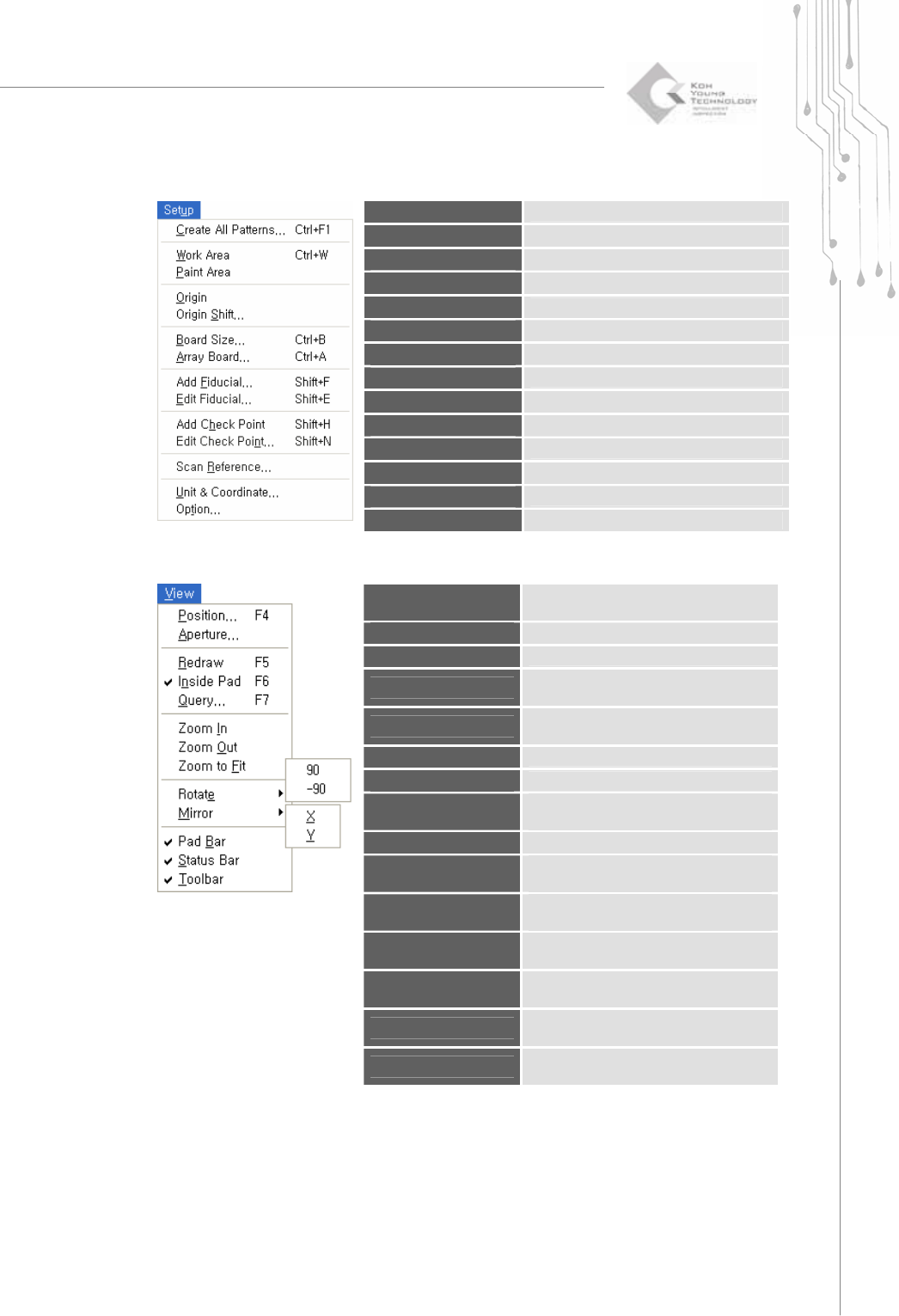
4) Setup Menu
Create All Patterns
Create all patterns automatically.
Work Area
Specify a work area.
Paint Area
Specify a paint area.
Origin
Specify the origin.
Origin Shift
Change the origin.
Board Size
Enter the board size.
Array Board
Enter or edit array board data.
Add Fiducial
Add new fiducial and Enter fiducial data .
Edit Fiducial
Edit fiducial data.
Add Check Point
Add a check point.
Edit Check Point
Edit a check point.
Scan Reference
Scan reference codes for a part.(not use)
Unit&Coordinate
Specify a unit and coordinate.
Option
Change default settings.
5) View Menu
Position
Select a pad or Flash or Trace for the
measuring a board size automatically.
Aperture
Open an aperture table.
Redraw
Redraw the main view screen.
Inside Pad
Specify whether flashes and traces will
be displayed inside a pad.
Query
Specify which items will be displayed in
the main view.
Zoom In
Zoom in the main view.
Zoom Out
Zoom out the main view.
Zoom to Fit
Set the zoom ratio for the main view to
100%.
Rotate
90: Rotate the main view clockwise by 90°.
Rotate
-90: Rotate the main view counter-
clockwise by 90°.
Mirror
X: Move the main view symmetrically
along the X-axis.
Mirror
Y: Move the main view symmetrically
along the Y-axis.
Pad Bar
Specify whether the pad bar will be
displayed.
Status Bar
Specify whether the status bar will be
displayed.
Toolbar
Specify whether the tool bar will be
displayed.