KY8030 Programmers Manual.pdf - 第81页
Programmers Manual | 79 define it in the Set CAD Format menu. a) Click “Tools ▶ SET CAD format”. Define CAD format dialog box will pop up. b) Open the CAD File by clickin g the “Auto Import Value from CAD” butt on. c) Se…
78 | KY-8030 Series(KYOS-2007001_rev0)
3DIn‐lineSolderPasteInspectionSystems
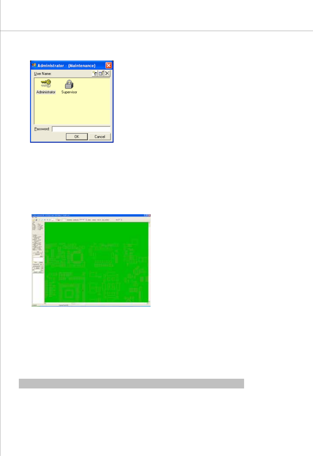
2) Select the desired user account, enter a password and click the OK button.
The CEditor program will be launched.
3) Click "File ▶ Load Pad file “or” File ▶ Load Job file” in the menu bar.
The file selection window will appear.
4) Select a pad file (*.pad) or a job file (*.mdb) and click the Open button. The selected
file will be opened.
5) In the menu bar;
Click “File ▶ Load CAD File” for component CAD, or
Click “File ▶ Load Pin CAD File” for pin CAD.
The file selection window will appear.
※ Note : When loading a CAD or pin CAD file format for the first time, you should
Programmers Manual
| 79
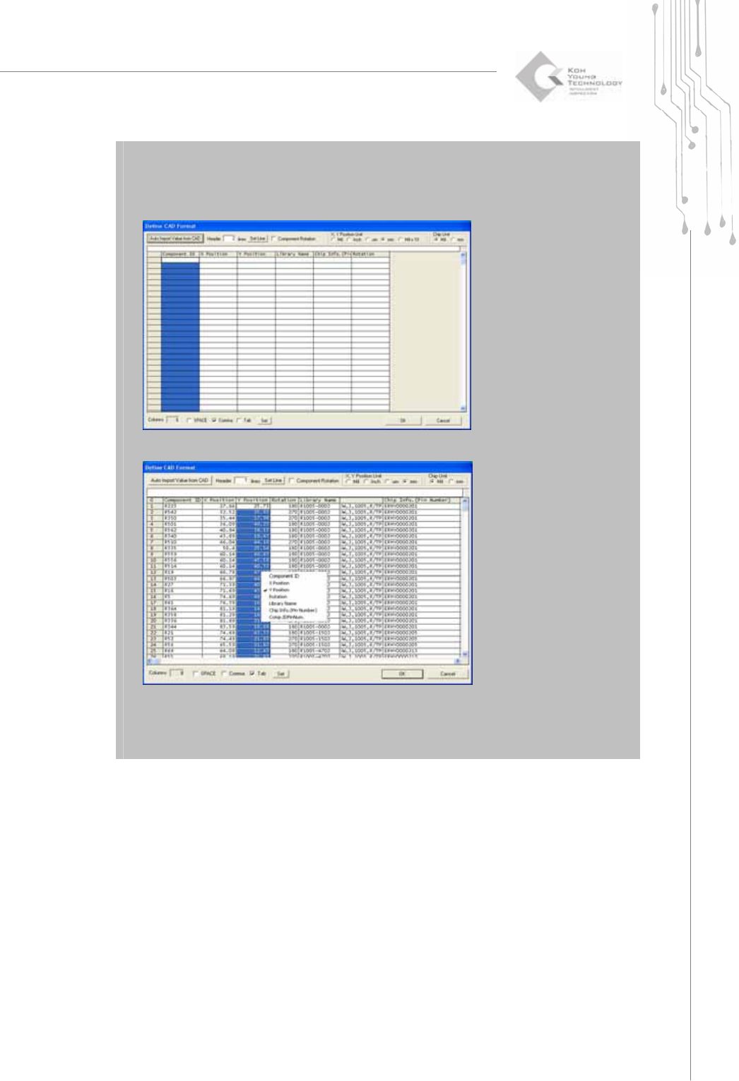
define it in the Set CAD Format menu.
a) Click “Tools ▶ SET CAD format”. Define CAD format dialog box will pop up.
b) Open the CAD File by clicking the “Auto Import Value from CAD” button.
c) Set each column to the corresponding item by left-clicking the mouse. Click OK
button.
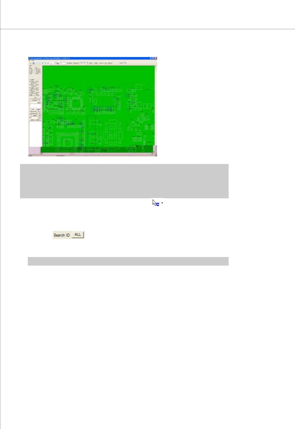
6) Select a Pin CAD file and click the OK button.
The selected file will be opened.
( The screen below shows the CAD file example)
80 | KY-8030 Series(KYOS-2007001_rev0)
3DIn‐lineSolderPasteInspectionSystems
※ Note: If the orientations of Pin CAD and pad files do not match, make sure that they have the same
orientation by using functions such as CAD Rotation +90 Degree, CAD Rotation -90
Degree, CAD Mirror X and CAD Mirror Y. It is marked with a blue box if it is component
CAD and with a pink cross if it is pin CAD.
7) If the CAD is not perfectly aligned to the pad, Select .
8) Move the CAD file or Pin CAD file to match it with the corresponding pad.
9) Modify the component box which is not matched in order to match all.
10) Click the
button under the “Search ID”. Assign a pin number to the
matched pin CAD and pad data and register it. Save the registered pin number in a
job file.
※ Note: Click the Not Find button under the "Search ID" to display unmatched data.
11) Click the CAD Refresh button or press the F5 key in the keyboard to display all
component and pin numbers.
12) Click the Save button to save the job data in a job file.
2.2.2. Creating a Job File When Loading Array Board CAD
1) Follow steps 1) - 11) in the previous example under 5.2.1.
2) Locate the reference positions for Boards 1 and 2.
1 2 3