KY8030 Programmers Manual.pdf - 第49页
Program mers Manual | 4 7 7) Array Board Open the "Array Board" dialog box to e dit array board data. The "Array Board" Dialog Box Shift X The X-coordinate of the shif ted array board Shift Y The Y-…
46 | KY-8030 Series(KYOS-2007001_rev0)
3DIn‐lineSolderPasteInspectionSystems
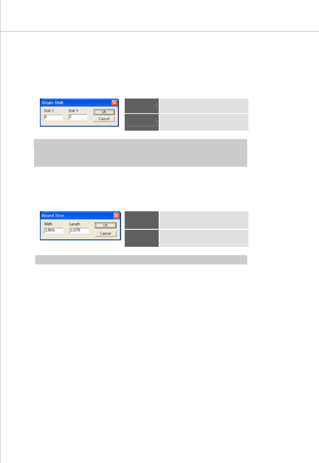
5) Origin Shift
Open the "Origin Shift" dialog box to change the position of the current origin.
The "Origin Shift" Dialog Box
Shift X
Displacement of the origin in the X-
axis.
Shift Y
Displacement of the origin in the Y-
axis.
※ Note:
y If you enter "0" for both Shift X and Shift Y, the position of the origin will not be changed.
y The origin will be moved by Shift X and Shift Y values along the PCB coordinates.
6) Board Size
Open the "Board Size" dialog box to enter the size of a PCB.
The "Board Size" Dialog Box
Width
The width of the PCB
Length
The length of the PCB.
※ Note: You can use the "Position" function to set the width and length values automatically.
Programmers Manual
| 47
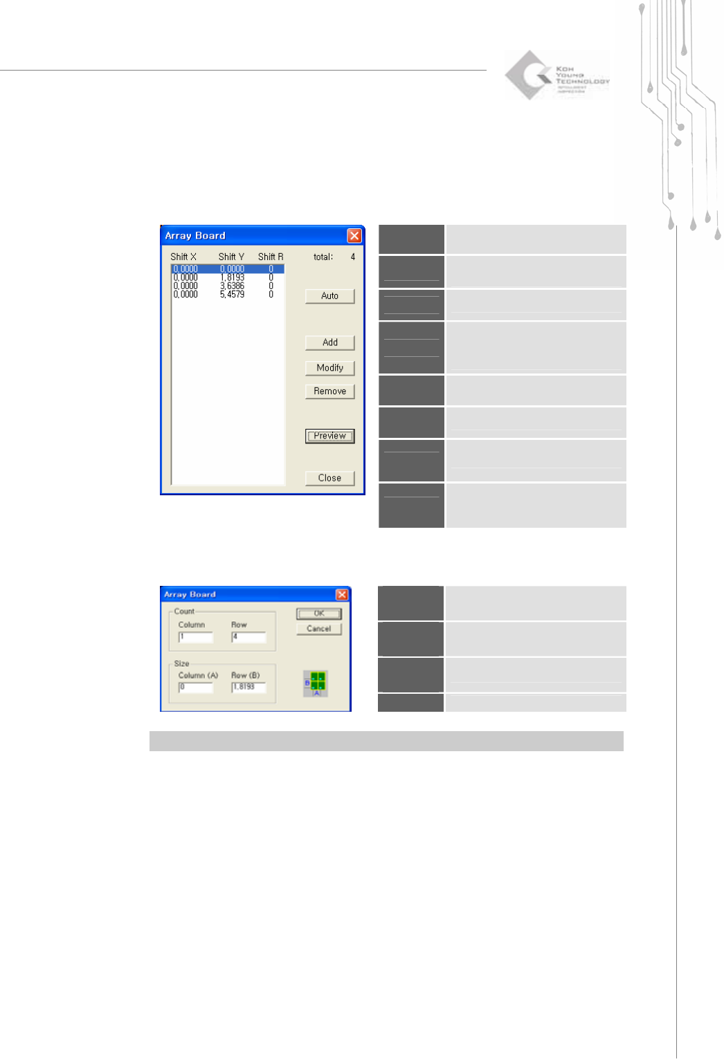
7) Array Board
Open the "Array Board" dialog box to edit array board data.
The "Array Board" Dialog Box
Shift X
The X-coordinate of the shifted
array board
Shift Y
The Y-coordinate of the shifted
array board
Shift R
The array board shift angle
Auto
Open the "Array Board (Auto)"
dialog box to specify the number
and size of array boards.
Add
Add an array board.
Modify
Modify the selected array board.
Remove
Remove the selected array board.
Preview
Use array board data to display
pads for the entire PCB in the
main view.
The "Array Board (Auto)" Dialog Box
Column
Count
The number of columns in an array
board
Row
Count
The number of rows in an array
board
Column
Size
The column size for an array board
Row Size
The row size for an array board
※ Note: You can use the "Position" function to set the column and row sizes automatically.
48 | KY-8030 Series(KYOS-2007001_rev0)
3DIn‐lineSolderPasteInspectionSystems
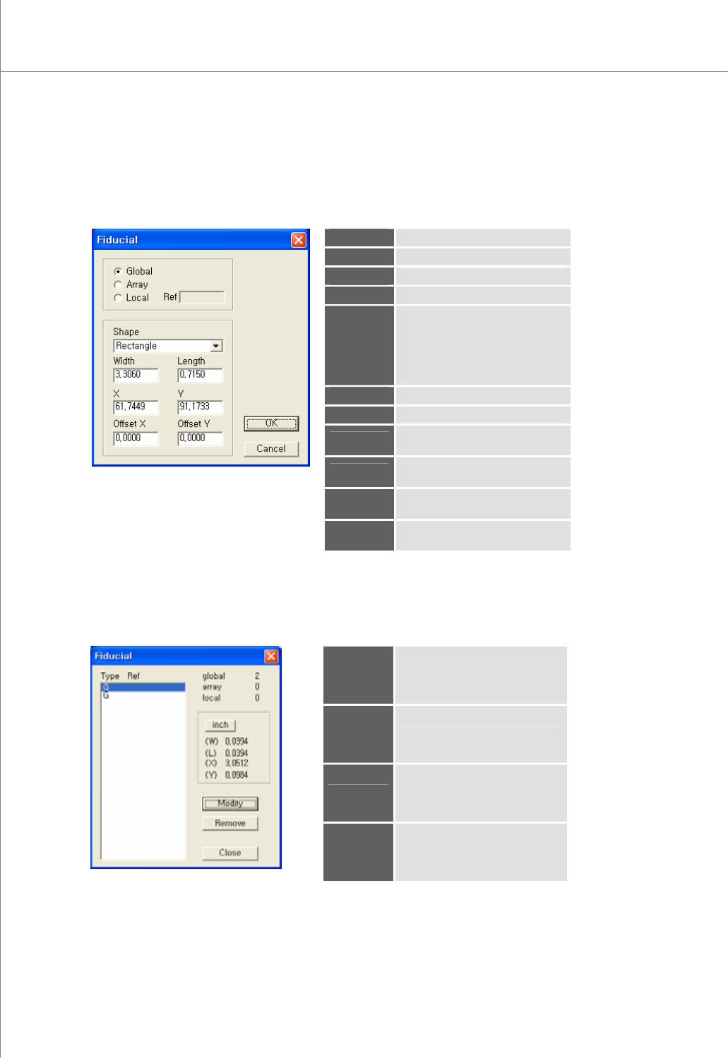
8) Add Fiducial (Shift+F)
Select a flash, trace or pad to register them as the fiducial.
The "Fiducial" Dialog Box
Global
The fiducial for a PCB
Array
The fiducial for an array board
Local
The fiducial for a part
Ref
Part reference code (local)
Shape
The shape of the fiducial.
Available Options: Rectangle,
Circle, Oblong, Rounded Rect.,
P-Slopped Rect., N-Slopped
Rect., Undefined
Width
The width of the fiducial
Length
The length of the pad
X
The center coordinate for the
fiducial in the X-axis
Y
The center coordinate for the
fiducial in the Y-axis
Offset X
The offset coordinate for the
fiducial in the X-axis
Offset Y
The offset coordinate for the
fiducial in the Y-axis
9) Edit Fiducial (Shift+E)
Open the "Fiducial" dialog box to edit fiducial data.
The "Fiducial" Dialog Box
Type
The fiducial type (G=Global,
A=Array, L=Local)
Ref
Part reference code (local)
Modify
Modify the selected fiducial.
※ Note: For more information,
see "4.8 Add Fiducial".
Remove
Remove the selected fiducial.