4OM-1322-006_w.pdf - 第72页
1-13 AKOEMT -ID 1004-003 3. Maintenance Spots 3. Maintenance Spots 3.1 Whole View Notice Any operations with a cover(s) being removed are included. After the maintenance work, be sure to attach the cover . Air Source Squ…

1-12
AKOEMT-ID
Table 4A12
Object Units
Inspection, Cleaning,
and Lubrication Spots
Work
Grease
Required Tools
Check
3.3.6
PCB Chuck Section
Backup Table Z-Axis
Guide Bushing
Lubrication DE1 Greasing Brush and
Spatula
Backup Table Z-Axis
Ball Screw
Lubrication DE1 Greasing Brush and
Spatula
Trapezoid Screw for
Chute Width Change
(Left Side), (Right Side)
Lubrication DE1 Greasing Brush and
Spatula
Linear Guide for Chute
Width Change
(Left Side), (Right Side)
Lubrication DE1 Greasing Brush and
Spatula
Linear Guide for PCB
Clamping
Lubrication DE1 Greasing Brush and
Spatula
3.3.7
Table Section
Table X-Axis Ball Screw Lubrication DE1 Greasing Brush and
Spatula
Table Z-Axis Ball Screw
Lubrication DE1 Greasing Brush and
Spatula
Table Z-Axis
Guide Bushing
Lubrication DE1 Greasing Brush and
Spatula
Table θ-Axis Ball Screw
Lubrication DE1 Greasing Brush and
Spatula
Table θ-Axis Linear
Guide
Lubrication DE1 Grease Gun and H Type
Table X-Axis
Linear Guide
(Front Left Side), (Front
Right Side), (Rear Side)
Lubrication DE1 Greasing Brush, Grease
Gun, U and P Types or
SPK-3C
3.3.9
Door Section
Front Door Gas Damper
(Upper)
Lubrication DE1 Greasing Brush, Grease
Gun, and P Type
Front Door Gas Damper
(Lower)
Lubrication DE1 Greasing Brush, Grease
Gun, and P Type
Rear Door Gas Damper
(Upper)
Lubrication DE1 Greasing Brush, Grease
Gun, and P Type
Rear Door Gas Damper
(Lower)
Lubrication DE1 Greasing Brush, Grease
Gun, and P Type
3.3.11
Control Box Section
(2places)
Fan Motor Cleaning DE1 Vacuume Cleaner, Brush
3.3.12
Main Body Section
Fan Motor Cleaning DE1 Vacuume Cleaner, Brush
3.3.13
Control
Computer Section
Fan Motor Cleaning DE1 Vacuume Cleaner
1004-004
2.5 Quarterly Maintenance
1-13
AKOEMT-ID
1004-003
3. Maintenance Spots
3. Maintenance Spots
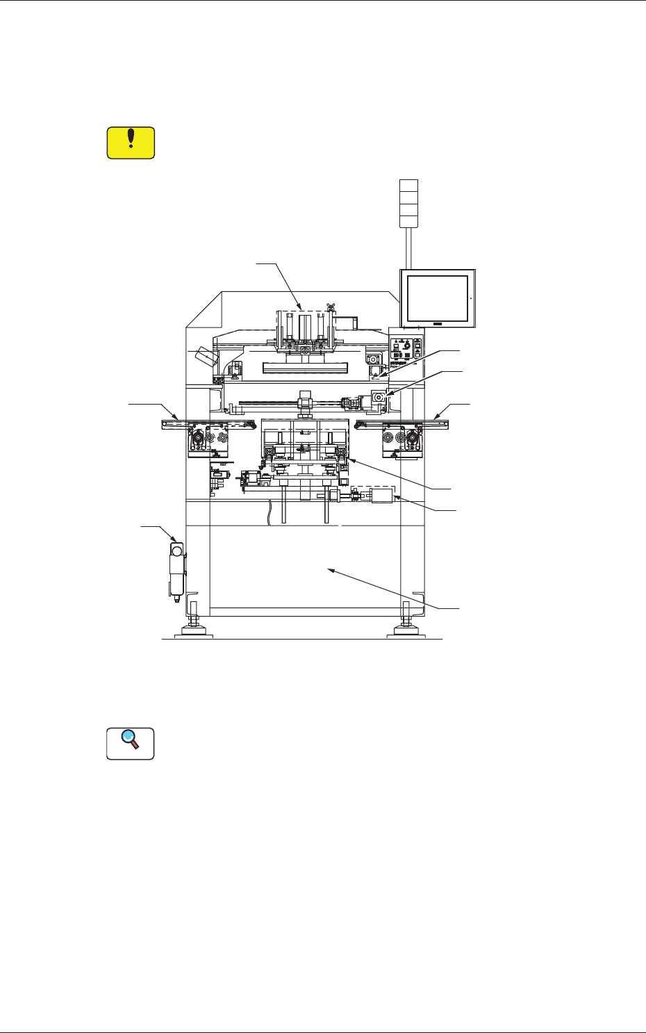
3.1 Whole View
Notice
Any operations with a cover(s) being removed are included.
After the maintenance work, be sure to attach the cover.
Air Source
Squeegee Head Section
Screen Holder Section
PEC Recognition Section
R Conveyor Section
(Output Conveyor Section)
PCB Chuck Section
Table Section
L Conveyor Section
(Input Conveyor Section)
Front Side of Machine
Control Computer Section
Fig. 4A3
Reference
(a) Refer to "3.3" and the subsequent items for the detailed information
on the spots of each section to be maintained and how to maintain
them.
(b) As for the options, refer to each instruction manual of the specially
specified devices for the maintenance.
1-14
AKOEMT-ID
1004-003
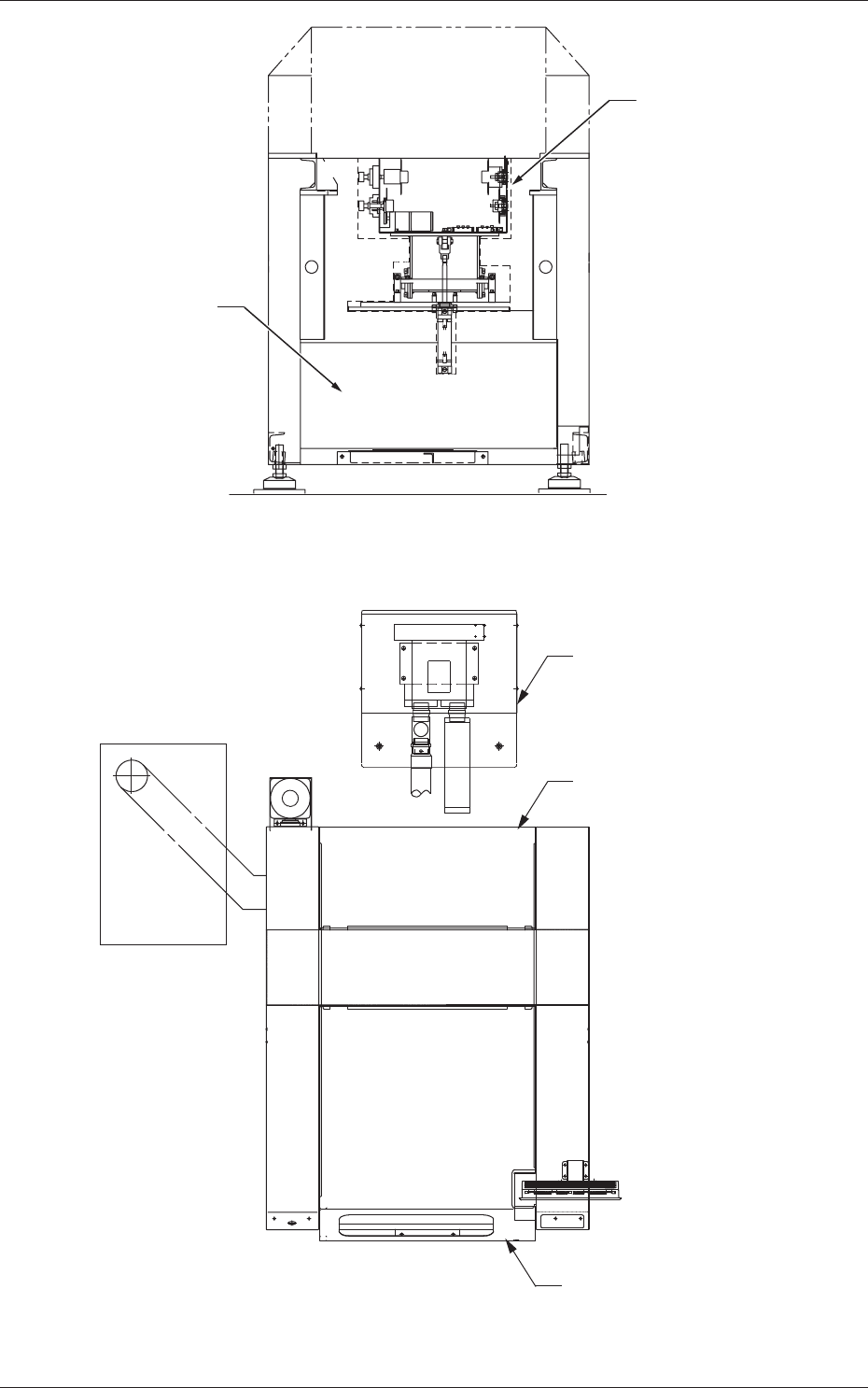
3.1 Whole View
Cleaning Section
Rear Side of Machine
Control Box Section
Fig. 4A4
Blower Unit (Vacuum Source)
Top View of Machine
Door Section (Rear Side)
Door Section (Front Side)
Fig. 4A5