00192405-02.pdf - 第134页
4 Component handling User Manual SIPLACE S-25 HM 4.3 Setting up the f eeder modules Software Version SR.502.xx 01/2001 US Edition 134 4 Fig. 4.3 - 1 Inserting 30 or 45 mm wide feeder modules on the component t able (1) F…

User Manual SIPLACE S-25 HM 4 Component handling
Software Version SR.502.xx 01/2001 US Edition 4.3 Setting up the feeder modules
133
4.3 Setting up the feeder modules
4.3.1 Preparing the component table and module for set-up
Å Select the setting range for the feeder module to be used
(see Vibrator configuration).
Å Move the placement head to the waiting position and press the emergency stop button.
Å Open the protective covers.
Å Clean the contact surface for the feeder modules and the contact surface for the feeder
modules on the component table.
Å Place the feeder module on the previously selected track on the component table (see Vi-
brator configuration).
4.3.2 Insert the module
Å
Insert the module so that the back of the module is held by the centering ball and the front
is fixed in place by the corresponding centering pin on the component table. Make sure that
the module is placed on the component table in the correct position for its width.
Å Check that the module is firmly seated on the component table.
Å Connect the module plug to the socket beneath the location.
PLEASE NOTE 4
When you connect the module, make sure that you use the right socket for the location
since the module receives the control pulse via this socket. The feeder module may not
work correctly if it is not connected to the right socket. 4
Å Close the protective covers and switch the control on again.
Å Carry out a refill check if necessary.
Å Continue placement.
4 Component handling User Manual SIPLACE S-25 HM
4.3 Setting up the feeder modules Software Version SR.502.xx 01/2001 US Edition
134
4
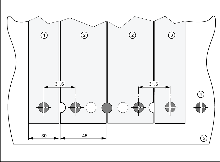
Fig. 4.3 - 1 Inserting 30 or 45 mm wide feeder modules on the component table
(1) Feeder module, 30 mm wide
(2) Feeder module, 45 mm wide
(3) Feeder module, 30 mm wide
(4) Centering ball
(5) Component table
User Manual SIPLACE S-25 HM 4 Component handling
Software Version SR.502.xx 01/2001 US Edition 4.4 Tape container
135
4.4 Tape container
4.4.1 Overview
Reels up to 15" in diameter may be used, although for 15" reels you should use spindles as
well. Insert the spindles into the partitions as shown in Fig. 4.4 - 1
. 4
PLEASE NOTE 4
We recommend that you use spindles if the tape reel diameter exceeds 5". This will ensure
that the feeder modules operate reliably. 4
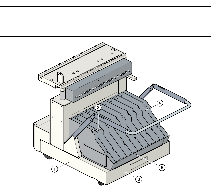
Fig. 4.4 - 1 Component table and tape container
(1) Component changeover table
(2) Spindle
(3) Waste tape container
(4) Partition
(5) Tape container