00192405-02.pdf - 第140页
4 Component handling User Manual SIPLACE S-25 HM 4.6 Component table, mobile Software Version SR.502.xx 01/2001 US Edition 140 4.6.2 Undocking the component t able 4 Fig. 4.6 - 2 Undocking the mobile c omponent
User Manual SIPLACE S-25 HM 4 Component handling
Software Version SR.502.xx 01/2001 US Edition 4.6 Component table, mobile
139
4.6 Component table, mobile
4.6.1 Safety instructions for docking and undocking the mobile component
table
WARNING 4
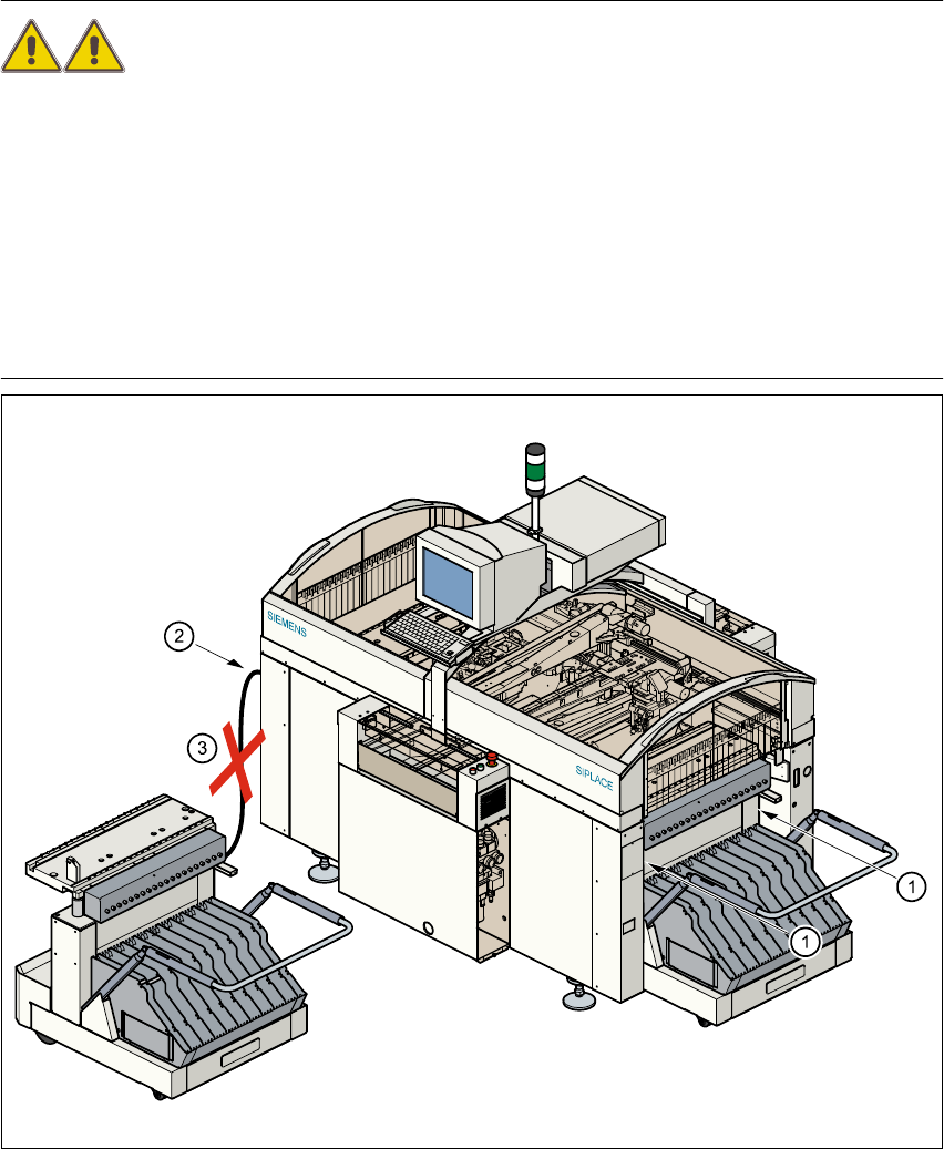
Å Never reach into the gap between the component tables and the placement system frame
while the machine is running (item 1).
Å Always check that the component table is docked on the placement system before connect-
ing or disconnecting the component table power cable at the socket on the placement sys-
tem (item 2).
Å NEVER connect the component table connecting cable to the socket on the placement sys-
tem and then operate the component table via the external compressed air control unit
(item 3).
Fig. 4.6 - 1 Safety instructions for the mobile component table
4 Component handling User Manual SIPLACE S-25 HM
4.6 Component table, mobile Software Version SR.502.xx 01/2001 US Edition
140
4.6.2 Undocking the component table
4
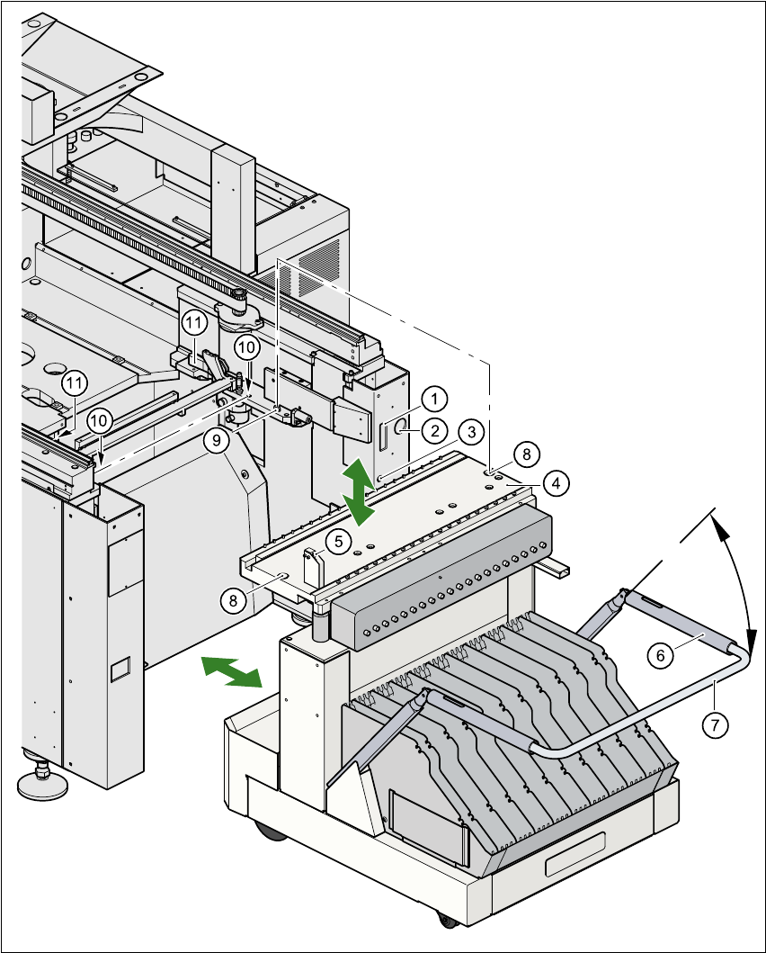
Fig. 4.6 - 2 Undocking the mobile component

User Manual SIPLACE S-25 HM 4 Component handling
Software Version SR.502.xx 01/2001 US Edition 4.6 Component table, mobile
141
Key to Fig. 4.6 - 2
(1) Communication interface connector
(2) Power supply connector for the component table
(3) Compressed air connection
(4) Component table bed
(5) Button for raising and lowering the component table bed
(6) Actuating tube
(7) Fold-down bracket
(8) Holes for the centering pins
(9) Centering pins
(10) Contact surfaces for the slide rails of the component table
(11) Horizontal tensioners
Å Click on the STOP PROCESSING PCB icon in the MAIN VIEW menu.
Å The PCB in progress will be completed. The icons of the SINGLE FUNCTIONS menu will
then be activated.
Å Click on the desired SINGLE FUNCTIONS GANTRY X icon (gantry 1 or 2).
Å Click on the GANTRY FUNCTIONS icon.
Å From this menu, click on the GO TO SET-UP POSITION button.
Å The selected placement head will move across the PCB transport to prevent it being dam-
aged when the component table is changed.
Å Open protective cover of the selected gantry.
Å Open the side screens.
Å Open the horizontal tensioners (item 11)
Å Pull the two actuating tubes (item 6) towards you at the same time and lift up the bracket
(item 7) to lock the raised component table bed in its top end position.
Å Hold down the button (item 5) for raising the component table bed (item 4) until the compo-
nent table bed reaches its top end position.
Å Unplug the component table power cable (item 2).
Å Unplug the component table control cable (item 1).
Å Disconnect the compressed air supply (item 3).
Å Remove the component table.