00192405-02.pdf - 第193页
User Manual SIPLACE S-25 HM Index 01/2001 US E dition 193 Index Numerics 12 mm S module for capacito rs based on powder ed metal , model C/D . . . . . . . . . 127 12 mm S module for capacito rs based on powder ed metal ,…
5 Station extensions User Manual SIPLACE S-25 HM
5.9 Nozzle changer for the 6-segment collect&place head Software Version SR.502.xx 01/2001 US Edition
192
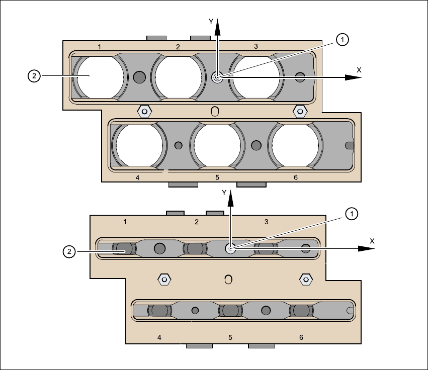
5.9.7 Position detection
There is a position detection fiducial on every magazine. 5
Fig. 5.9 - 5 Nozzle changer - position detection
(1) Positioning fiducial
(2) Position of the nozzles in the magazine with respect to the positioning fiducial
5

User Manual SIPLACE S-25 HM Index
01/2001 US Edition
193
Index
Numerics
12 mm S module for capacitors based
on powdered metal, model C/D
. . . . . . . . .127
12 mm S module for capacitors based
on powdered metal, model E
. . . . . . . . . . .128
12/16 mm S module
. . . . . . . . . . . . . . . . . . . . .126
12-segment collect&place head
. . . . . . . . . . . . .20
angular accuracy
. . . . . . . . . . . . . . . . . 20, 39
component specification
. . . . . . . . . . . . . . . .39
component vision module
. . . . . . . . . . . . . . .38
description
. . . . . . . . . . . . . . . . . . . . . . . . . .39
max. placement rate
. . . . . . . . . . . . . . . . . . .39
maximum stroke of the Z axis
. . . . . . . . . . .39
motor for "Reject" valve
adjustment drive
. . . . . . . . . . . . . . . . . . . . . .38
nozzle types
. . . . . . . . . . . . . . . . . . . . . . . . .39
placement accuracy
. . . . . . . . . . . . . . . 20, 39
programmable set-down force
. . . . . . . . . . .39
range of components
. . . . . . . . . . . . . . . . . .39
star motor
. . . . . . . . . . . . . . . . . . . . . . . . . . .38
star with 12 sleeves
. . . . . . . . . . . . . . . . . . .38
structure
. . . . . . . . . . . . . . . . . . . . . . . . . . . .38
technical data
. . . . . . . . . . . . . . . . . . . . . . . .39
turning station
. . . . . . . . . . . . . . . . . . . . . . . .38
Z-axis drive
. . . . . . . . . . . . . . . . . . . . . . . . . .38
24/32 mm S module
. . . . . . . . . . . . . . . . . . . . .129
3 x 8 mm S module
. . . . . . . . . . . . . . . . . . . . . .124
3 x 8 mm S module for 0201/0402
components
. . . . . . . . . . . . . . . . . . . . . . . .125
44 mm S module
. . . . . . . . . . . . . . . . . . . . . . . .130
6/12-segment collect&place head
. . . . . . . . . . . .18
6-segment collect&place head
. . . . . . . . . . . . . .20
angular accuracy
. . . . . . . . . . . . . . . . . . . . .41
component range
. . . . . . . . . . . . . . . . . . . . .41
component specification
. . . . . . . . . . . . . . . .41
description
. . . . . . . . . . . . . . . . . . . . . . . . . .41
max. placement rate
. . . . . . . . . . . . . . . . . . .41
max. stroke of the Z axis
. . . . . . . . . . . . . . .41
motor for "Reject" valve
adjustment drive
. . . . . . . . . . . . . . . . . . . . . 40
nozzle types
. . . . . . . . . . . . . . . . . . . . . . . . 41
placement accuracy
. . . . . . . . . . . . . . . 20, 41
programmable set-down force
. . . . . . . . . . 41
standard vision module
. . . . . . . . . . . . . . . . 40
star motor
. . . . . . . . . . . . . . . . . . . . . . . . . . 40
star with 6 sleeves
. . . . . . . . . . . . . . . . . . . 40
turning station
. . . . . . . . . . . . . . . . . . . . . . . 40
with standard component vision
module, structure
. . . . . . . . . . . . . . . . . . . . 40
with standard component vision
module, technical data
. . . . . . . . . . . . . . . . 41
Z axis driving mechanism
. . . . . . . . . . . . . . 40
8 mm S II module
. . . . . . . . . . . . . . . . . . . . . . 123
A
adjustment structure
. . . . . . . . . . . . . . . . . . . . 175
admissible load per unit area on foundation
. . . 25
affected employees
. . . . . . . . . . . . . . . . . . . . . . 90
ambient factors, permissible
. . . . . . . . . . . . . . . 24
asynchronous conveyor mode
. . . . . . . . . . . . 164
description
. . . . . . . . . . . . . . . . . . . . . . . . 164
function
. . . . . . . . . . . . . . . . . . . . . . . . . . . 164
atmospheric humidity
. . . . . . . . . . . . . . . . . . . . 24
authorized employees
. . . . . . . . . . . . . . . . . . . . 90
B
bulk case feeder
. . . . . . . . . . . . . . . . . . . . . . . 132
C
CAUTION
. . . . . . . . . . . . . . . . . . . . . . . . . . . . . 47
center conveyor
. . . . . . . . . . . . . . . . . . . . . . . . . 44
center of gravity
. . . . . . . . . . . . . . . . . . . . . . . . . 26
centering pin
. . . . . . . . . . . . . . . . . . . . . . . . . . 133
ceramic substrate centering
base
. . . . . . . . . . . . . . . . . . . . . . . . . . . . . 174
centering types
. . . . . . . . . . . . . . . . . . . . . 172
connecting nozzle
. . . . . . . . . . . . . . . . . . . 174
fiducial shape
. . . . . . . . . . . . . . . . . . . . . . 176

Index User Manual SIPLACE S-25 HM
01/2001 US Edition
194
general
. . . . . . . . . . . . . . . . . . . . . . . . . . . 172
general overview
. . . . . . . . . . . . . . . . . . . 173
maintenance
. . . . . . . . . . . . . . . . . . . . . . . 174
mechanical centering
. . . . . . . . . . . . . . . . 172
normal lighting
. . . . . . . . . . . . . . . . . . . . . 172
oblique lighting
. . . . . . . . . . . . . . . . . . . . . 175
sensor
. . . . . . . . . . . . . . . . . . . . . . . . . . . . 174
technical data
. . . . . . . . . . . . . . . . . . . . . . 175
transport type
. . . . . . . . . . . . . . . . . . . . . . 172
change shift
. . . . . . . . . . . . . . . . . . . . . . . . . . . 104
changing feeder modules
. . . . . . . . . . . . . . . . 110
changing jobs
. . . . . . . . . . . . . . . . . . . . . . . . . 103
changing the ceramic substrate on the PCB
. . 172
changing the conveyor mode
. . . . . . . . . . . . . 164
changing the set-up
. . . . . . . . . . . . . . . . . . . . . 110
CO vision module on the
12-segment collect&place head
component dimensions
. . . . . . . . . . . . . . . . 42
field of vision
. . . . . . . . . . . . . . . . . . . . . . . . 42
illumination method
. . . . . . . . . . . . . . . . . . . 42
min. lead pitch
. . . . . . . . . . . . . . . . . . . . . . 42
range of components
. . . . . . . . . . . . . . . . . 42
technical data
. . . . . . . . . . . . . . . . . . . . . . . 42
CO vision module(standard) on the
6-segment collect&place head
component dimensions
. . . . . . . . . . . . . . . . 43
component range
. . . . . . . . . . . . . . . . . . . . 43
field of view
. . . . . . . . . . . . . . . . . . . . . . . . . 43
method of illumination
. . . . . . . . . . . . . . . . . 43
minimum lead pitch
. . . . . . . . . . . . . . . . . . . 43
technical data
. . . . . . . . . . . . . . . . . . . . . . . 43
communications connection for
component changeover table
. . . . . . . . . . . 22
component barcode
. . . . . . . . . . . . . . . . . . . . 159
components
. . . . . . . . . . . . . . . . . . . . . . . 160
general
. . . . . . . . . . . . . . . . . . . . . . . . . . . 159
illegible barcode
. . . . . . . . . . . . . . . . . . . . 162
notes on operation
. . . . . . . . . . . . . . . . . . 161
operation
. . . . . . . . . . . . . . . . . . . . . . . . . . 162
technical data
. . . . . . . . . . . . . . . . . . . . . . 162
track allocation
. . . . . . . . . . . . . . . . . . . . . 160
component barcode reader
. . . . . . 32, 33, 34, 159
connected to
. . . . . . . . . . . . . . . . . . . . . . . . 34
data entry
. . . . . . . . . . . . . . . . . . . . . . . . . . 34
filter for suppressing data
. . . . . . . . . . . . . . 34
not permissible
. . . . . . . . . . . . . . . . . . . . . . 34
number of barcodes
. . . . . . . . . . . . . . . . . . 34
number of characters
. . . . . . . . . . . . . . . . . 34
preset code types
. . . . . . . . . . . . . . . . . . . . 34
component barcode reader, technical data
. . . . 34
component coordinate system
. . . . . . . . . . . . 117
component counter
. . . . . . . . . . . . . . . . 30, 31, 77
component handling, overview
. . . . . . . . . . . . 121
component supply
. . . . . . . . . . . . . . . . . . . . . . . 20
component table, preparing
. . . . . . . . . . . . . . . 133
compressed air consumption
. . . . . . . . . . . . . . 24
compressed air pressure
. . . . . . . . . . . . . . . . . . 24
compressed air specification
. . . . . . . . . . . . . . . 24
compressed air supply
. . . . . . . . . . . . . . . . 24, 28
compressed air supply connection for the
component changeover table
. . . . . . . . . . . 22
compressed air unit
. . . . . . . . . . . . . . . . 22, 78, 86
configuring the PCB barcode reader
. . . . . . . . 170
connection
. . . . . . . . . . . . . . . . . . . . . . . . . . . . . 20
connection data
. . . . . . . . . . . . . . . . . . . . . . . . . 22
connection for compressed air line
. . . . . . . . . . 22
connection points, electrical
. . . . . . . . . . . . . . . 22
connection points, pneumatic
. . . . . . . . . . . . . . 22
console on the central cross-beam
. . . . . . . . . . 32
control pulse
. . . . . . . . . . . . . . . . . . . . . . . . . . 133
control unit
. . . . . . . . . . . . . . . . . . . . . . . . . . . . . 86
controls
. . . . . . . . . . . . . . . . . . . . . . . . . . . . . . . 30
controls, description
. . . . . . . . . . . . . . . . . . . . . 31
controls, overview
. . . . . . . . . . . . . . . . . . . . . . . 30
conventions of hazard symbols
. . . . . . . . . . . . . 47
conveyor height
. . . . . . . . . . . . . . . . . . . . . . . . . 27
conveyor mode
asynchronous
. . . . . . . . . . . . . . . . . . . . . . 164
D
DANGER
. . . . . . . . . . . . . . . . . . . . . . . . . . . . . . 47
defining the transport tracks
. . . . . . . . . . . . . . 164
description of the 12-segment
collect&place head
. . . . . . . . . . . . . . . . . . . 39
description of the 6-segment
collect&place head
. . . . . . . . . . . . . . . . . . . 41
description of the machine
. . . . . . . . . . . . . . . . 18
description, controls
. . . . . . . . . . . . . . . . . . . . . 31
description, functional
. . . . . . . . . . . . . . . . . . . . 18