00192405-02.pdf - 第173页
User Manual SIPLAC E S-25 HM 5 Station extensions Software Vers ion SR.502.xx 01/2001 US Edition 5.5 Ceramic substrate ce ntering 173 Fig. 5.5 - 1 General overview (plan view)

5 Station extensions User Manual SIPLACE S-25 HM
5.5 Ceramic substrate centering Software Version SR.502.xx 01/2001 US Edition
172
5.5 Ceramic substrate centering
5.5.1 General
The ceramic substrate can be centered either mechanically or optically. 5
With optical centering, the fiducials can be detected with either normal or oblique lighting. 5
5.5.2 Possible centering types
The following centering types for ceramic substrates can be entered in the transport type machine
data (REAL.MA). 5
5.5.3 Mechanical centering
5.5.3.1 General
Mechanical substrate centering is used to lock ceramic substrates firmly in position in the X and
Y directions in such a way that the material is not damaged. Ceramic substrates can also be
placed right up to the edge. 5
5.5.3.2 Changing the ceramic substrate on the PCB
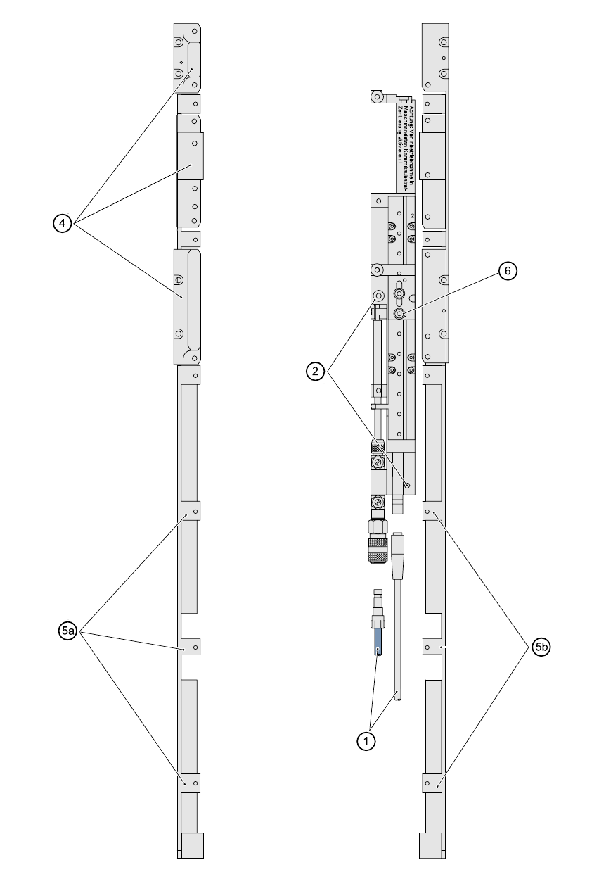
Å Disconnect the air line and power cable (see point 1 in Fig. 5.5 - 1).
Å Remove the ceramic substrate centering (see point 2 in Fig. 5.5 - 1).
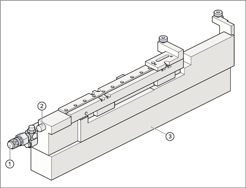
Å Detach the base of the ceramic substrate centering unit (see point 3 in Fig. 5.5 - 2).
Å Remove the three clamping parts (see point 4 in Fig. 5.5 - 1), and fit the standard guide at this
point.
Å Fit the hold-down bracket (see point 5a and 5b in Fig. 5.5 - 1).
Å Adjust the size of the PCB (see point 6 in Fig. 5.5 - 1).
Å Use the SITEST program to edit the transport type (see table in Section 5.5.2) in the machine
data.
Transport type Centering
4 Mechanical substrate centering with normal lighting
5 Oblique lighting only with Y axis PCB clamping unit
6 Mechanical substrate centering with oblique lighting
User Manual SIPLACE S-25 HM 5 Station extensions
Software Version SR.502.xx 01/2001 US Edition 5.5 Ceramic substrate centering
173
Fig. 5.5 - 1 General overview (plan view)
5 Station extensions User Manual SIPLACE S-25 HM
5.5 Ceramic substrate centering Software Version SR.502.xx 01/2001 US Edition
174
Fig. 5.5 - 2 Ceramic substrate centering (side view)
(1) Connecting nozzle
(2) ‘Ceramic substrate centering’ sensor
(3) Base
5.5.3.3 Maintenance
– Clean and grease the ball race in the X-axis centering unit.
– If necessary, check that the pneumatic driving mechanism is running smoothly.
– The conveyor should be maintained as described in the maintenance instructions.