00192405-02.pdf - 第165页
User Manual SIPLAC E S-25 HM 5 Station extensions Software Vers ion SR.502.xx 01/2001 US Edition 5.3 Dual conv eyor 165 5.3.6 Automatic wid th adjustment on the dual conveyor PLEA SE NOT E 5 The con veyor set point width…

5 Station extensions User Manual SIPLACE S-25 HM
5.3 Dual conveyor Software Version SR.502.xx 01/2001 US Edition
164
There are two conveyor modes: "Single conveyor" and "Dual conveyor asynchronous. Enter the
conveyor mode you wish to use in the machine data (konfig.ma). 5
5.3.3 Defining the transport tracks
The right transport track (viewed in the transport direction) is designated "Transport 1" and the left
as "Transport 2" (see Fig. 5.3 - 1
). 5
5.3.4 Changing the conveyor mode
5.3.5 Asynchronous conveyor mode
5.3.5.1 Description
In asynchronous mode, only one PCB in a transport track is processed. At the same time, another
PCB in the second transport track is moved into the placement position. This saves the full con-
veying time of one PCB, thus considerably increasing performance, particularly for PCBs with a
short cycle time. 5
5.3.5.2 Function
Once the machine has received the job data (cluster, set-up), the PCBs on the feeding belts are
continuously transported to the available center conveyor (provided that the center conveyor is
free) throughout the placement operation. The placement sequence starts as soon as a PCB has
moved onto the center conveyor. The PCBs are processed one after another. 5
PLEASE NOTE 5
The components to be placed and the width of the PCBs must be identical on transport track 1
and 2. 5
If the placement sequence is interrupted, the conveyor interface will be disabled and the PCBs
currently on the center conveyor will be completed. 5
The conveyor interface is disabled or enabled simultaneously for both transport tracks. 5
Conveyor mode Input in konfig.ma
Single conveyor 0
Dual conveyor asynchronous 2

User Manual SIPLACE S-25 HM 5 Station extensions
Software Version SR.502.xx 01/2001 US Edition 5.3 Dual conveyor
165
5.3.6 Automatic width adjustment on the dual conveyor
PLEASE NOTE 5
The conveyor setpoint width relates to both conveyor belts. When the command is received, the
conveyor belts are set to the setpoint width one after another. 5
5.3.7 Technical data – dual conveyor system
5
5.3.8 Maintenance
The individual conveyor belts and the additional lifting table require the same maintenance as the
standard conveyor. Each conveyor belt must be maintained as described in the maintenance in-
structions. 5
PCB format
(length x width)
50mm x 50mm to 460mm x 216mm
(2" x 2" to 18" x 8.5")
Optionally:
50 mm x 50 mm up to 508mm x 216mm
(2" x 2" up to 20" x 8.5 ")
PCB thickness 0.5mm to 4.5mm
Max. PCB warpage On top: 4.5mm - PCB thickness
On bottom: 0.5mm + PCB thickness
Clearance on PCB underside 25mm (standard), 40mm (option)
PCB transport height 830mm ± 15mm (standard)
900mm ± 15mm (option)
930mm ± 15mm (option)
950mm ± 15mm (SMEMA: optional)
Stationary conveyor side Right (standard), left (optional)
Type of interface Siemens (standard), (SMEMA: optional)
Component-free handling edge 3mm
PCB changeover time 2.5 s
Type of transportation asynchronous
Components on each conveyor same
PCB width on each conveyor same
Ink spot recognition possible
Automatic width adjustment possible
5 Station extensions User Manual SIPLACE S-25 HM
5.4 PCB barcode Software Version SR.502.xx 01/2001 US Edition
166
5.4 PCB barcode
5.4.1 Overview
The PCB barcode reader is used to automatically record and decode barcodes on PCBs. The
PCB barcode reader sends the read data via its serial interface to the machine controller for fur-
ther processing. 5
The PCB barcode readers are installed on the input side of the placement machine, above and
below the PCB conveyor, so that barcode labels on the topside and underside of the PCBs can
be read.
One or two PCB barcode readers may be retrofitted in order to read the topside and underside of
the PCB on the transport track. 5
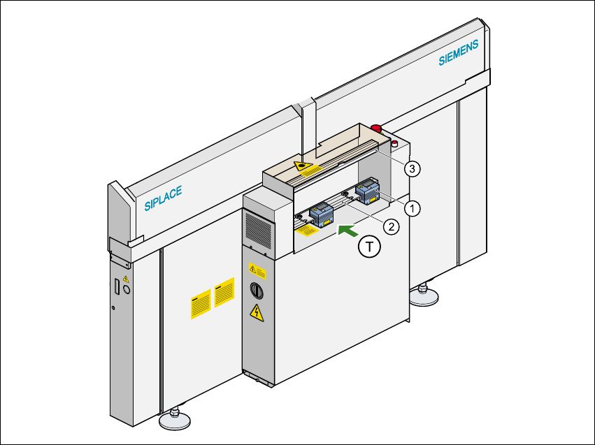
Fig. 5.4 - 1 Position of the modules on the input side of the placement machine
(1) PCB barcode reading head
(2) Profiled rail for ‘underside’ PCB barcode reader
(3) Profiled rail for ‘topside’ PCB barcode reader
(T) Direction of PCB transport 5