00192405-02.pdf - 第18页
1 Introduction, technical data User Manual SIPLACE S -25 HM 1.5 Description of t he machine Software Vers ion SR.502.xx 01/2001 US E dition 18 1.5 Description of the mac hine 1.5.1 Functional description The autom atic p…

User Manual SIPLACE S-25 HM 1 Introduction, technical data
Software Version SR.502.xx 01/2001 US Edition 1.4 Revision index
17
1.4 Revision index
1
Manual Software version Edition
First version User Manual SR.502.xx 11/2000 US
First edition User Manual SR.502.xx 01/2001 US
1 Introduction, technical data User Manual SIPLACE S-25 HM
1.5 Description of the machine Software Version SR.502.xx 01/2001 US Edition
18
1.5 Description of the machine
1.5.1 Functional description
The automatic placement system is a high-performance placement system with two gantries. A
PCB vision module and a 6 or 12-segment collect&place-head are mounted on each gantry. Col-
lect&place heads equipped with a component vision module pick up the components (CO) from
stationary feeder modules and place them onto the PCB clamped in the PCB conveyor. 1
1
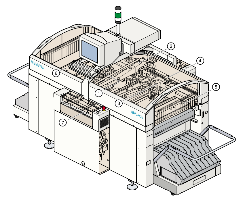
Fig. 1.5 - 1 Overall view of the placement system
(1) 6/12-segment collect&place head with component vision module (gantry 1)
(2) Gantry 1 with PCB vision module
(3) 6/12-segment collect&place head with component vision module (gantry 2)
(4) Gantry 2 with PCB vision module
(5) Stationary component supply (location 1)
(6) Stationary component supply (location 3)
(7) PCB conveyor (dual conveyor option)

User Manual SIPLACE S-25 HM 1 Introduction, technical data
Software Version SR.502.xx 01/2001 US Edition 1.5 Description of the machine
19
The concept behind the automatic placement system 1
– with its stationary feeder modules,
– PCBs that do not move during placement
– and positionable placement heads
has a number of significant benefits: 1
– For example, the flexible 6/12-segment collect&place heads combined with automatic nozzle
changers enable the nozzle configuration to be changed temporarily and automatically
adapted to receive different component sizes. You can also optimize the traversing paths and
the placement sequence.
– With stationary feeder modules, even the tiniest components are picked up reliably.
– The components cannot slip on the PCB during placement (as is often the case with moving
PCBs) since the PCB does not move.
– Sophisticated optical centering systems (vision modules) for components and PCBs also en-
sure high component positioning accuracy.
– Components can be topped up and tapes can be spliced without stopping the machine.
– Prepared component tables enable the placement system to be retooled without long stop-
pages.
1.5.2 Head Modularity concept (HM)
The abbreviation HM in the designation of the SIPLACE S-25 HM placement system stands for
Head Modularity. 1
This concept allows any combination of 6-nozzle and 12-nozzle collect&place heads to be used
on the placement system. A simple head change procedure will enable the system to be quickly
adapted to the requirements of individual placement jobs. 1