00192405-02.pdf - 第192页
5 Station extensions User Manual S IPLACE S-25 H M 5.9 Nozzle changer for the 6-segment collect&place head S oftware Version SR .502.xx 01/2001 US Edition 192 5.9.7 Position detection There is a positio n detec tion …
User Manual SIPLACE S-25 HM 5 Station extensions
Software Version SR.502.xx 01/2001 US Edition 5.9 Nozzle changer for the 6-segment collect&place head
191
5.9.6 Changing the magazine
Å
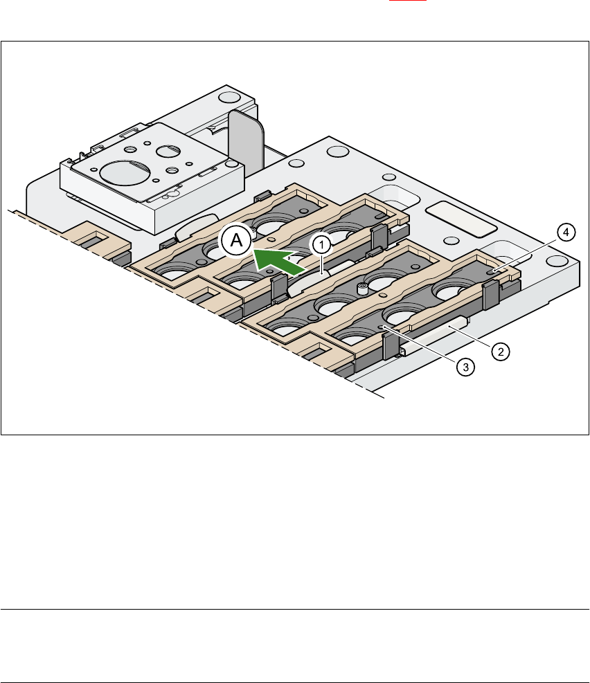
To remove the magazine, push the spring hook (item 1 in Fig. 5.9 - 4) away from the magazine.
Lift the magazine out of the carrier.
Fig. 5.9 - 4 Changing the magazine
(1) Spring hook
(2) Retaining clamp
(3) Centering hole
(4) Slot
(A) Push the spring hook away from the magazine 5
PLEASE NOTE
Make sure that you insert the magazine so that the centering pins slide into the centering hole
(item 3) and slot (item 4). 5
Å Then place the side of the magazine with the centering hole (item 3) and slot (item 4) on the
carrier. The two knobs on the magazine must slide into the retaining clamp (item 2).
Å Push the spring hook away from the magazine.
Å Press the magazine so that it lies flat on the carrier, then release the spring hook. The spring
hook must latch into place.
5 Station extensions User Manual SIPLACE S-25 HM
5.9 Nozzle changer for the 6-segment collect&place head Software Version SR.502.xx 01/2001 US Edition
192
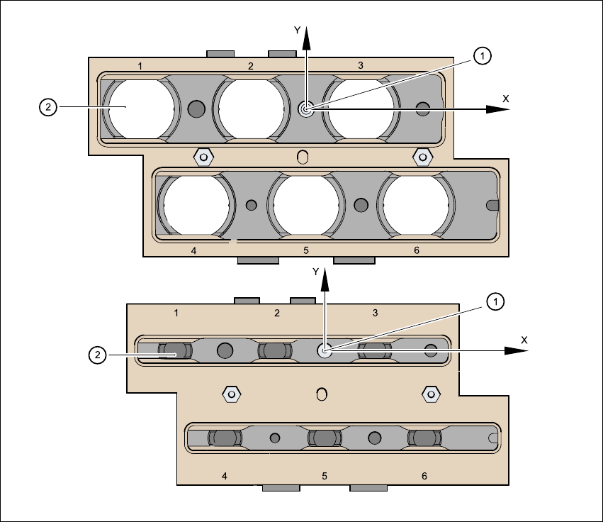
5.9.7 Position detection
There is a position detection fiducial on every magazine. 5
Fig. 5.9 - 5 Nozzle changer - position detection
(1) Positioning fiducial
(2) Position of the nozzles in the magazine with respect to the positioning fiducial
5

User Manual SIPLACE S-25 HM Index
01/2001 US Edition
193
Index
Numerics
12 mm S module for capacitors based
on powdered metal, model C/D
. . . . . . . . .127
12 mm S module for capacitors based
on powdered metal, model E
. . . . . . . . . . .128
12/16 mm S module
. . . . . . . . . . . . . . . . . . . . .126
12-segment collect&place head
. . . . . . . . . . . . .20
angular accuracy
. . . . . . . . . . . . . . . . . 20, 39
component specification
. . . . . . . . . . . . . . . .39
component vision module
. . . . . . . . . . . . . . .38
description
. . . . . . . . . . . . . . . . . . . . . . . . . .39
max. placement rate
. . . . . . . . . . . . . . . . . . .39
maximum stroke of the Z axis
. . . . . . . . . . .39
motor for "Reject" valve
adjustment drive
. . . . . . . . . . . . . . . . . . . . . .38
nozzle types
. . . . . . . . . . . . . . . . . . . . . . . . .39
placement accuracy
. . . . . . . . . . . . . . . 20, 39
programmable set-down force
. . . . . . . . . . .39
range of components
. . . . . . . . . . . . . . . . . .39
star motor
. . . . . . . . . . . . . . . . . . . . . . . . . . .38
star with 12 sleeves
. . . . . . . . . . . . . . . . . . .38
structure
. . . . . . . . . . . . . . . . . . . . . . . . . . . .38
technical data
. . . . . . . . . . . . . . . . . . . . . . . .39
turning station
. . . . . . . . . . . . . . . . . . . . . . . .38
Z-axis drive
. . . . . . . . . . . . . . . . . . . . . . . . . .38
24/32 mm S module
. . . . . . . . . . . . . . . . . . . . .129
3 x 8 mm S module
. . . . . . . . . . . . . . . . . . . . . .124
3 x 8 mm S module for 0201/0402
components
. . . . . . . . . . . . . . . . . . . . . . . .125
44 mm S module
. . . . . . . . . . . . . . . . . . . . . . . .130
6/12-segment collect&place head
. . . . . . . . . . . .18
6-segment collect&place head
. . . . . . . . . . . . . .20
angular accuracy
. . . . . . . . . . . . . . . . . . . . .41
component range
. . . . . . . . . . . . . . . . . . . . .41
component specification
. . . . . . . . . . . . . . . .41
description
. . . . . . . . . . . . . . . . . . . . . . . . . .41
max. placement rate
. . . . . . . . . . . . . . . . . . .41
max. stroke of the Z axis
. . . . . . . . . . . . . . .41
motor for "Reject" valve
adjustment drive
. . . . . . . . . . . . . . . . . . . . . 40
nozzle types
. . . . . . . . . . . . . . . . . . . . . . . . 41
placement accuracy
. . . . . . . . . . . . . . . 20, 41
programmable set-down force
. . . . . . . . . . 41
standard vision module
. . . . . . . . . . . . . . . . 40
star motor
. . . . . . . . . . . . . . . . . . . . . . . . . . 40
star with 6 sleeves
. . . . . . . . . . . . . . . . . . . 40
turning station
. . . . . . . . . . . . . . . . . . . . . . . 40
with standard component vision
module, structure
. . . . . . . . . . . . . . . . . . . . 40
with standard component vision
module, technical data
. . . . . . . . . . . . . . . . 41
Z axis driving mechanism
. . . . . . . . . . . . . . 40
8 mm S II module
. . . . . . . . . . . . . . . . . . . . . . 123
A
adjustment structure
. . . . . . . . . . . . . . . . . . . . 175
admissible load per unit area on foundation
. . . 25
affected employees
. . . . . . . . . . . . . . . . . . . . . . 90
ambient factors, permissible
. . . . . . . . . . . . . . . 24
asynchronous conveyor mode
. . . . . . . . . . . . 164
description
. . . . . . . . . . . . . . . . . . . . . . . . 164
function
. . . . . . . . . . . . . . . . . . . . . . . . . . . 164
atmospheric humidity
. . . . . . . . . . . . . . . . . . . . 24
authorized employees
. . . . . . . . . . . . . . . . . . . . 90
B
bulk case feeder
. . . . . . . . . . . . . . . . . . . . . . . 132
C
CAUTION
. . . . . . . . . . . . . . . . . . . . . . . . . . . . . 47
center conveyor
. . . . . . . . . . . . . . . . . . . . . . . . . 44
center of gravity
. . . . . . . . . . . . . . . . . . . . . . . . . 26
centering pin
. . . . . . . . . . . . . . . . . . . . . . . . . . 133
ceramic substrate centering
base
. . . . . . . . . . . . . . . . . . . . . . . . . . . . . 174
centering types
. . . . . . . . . . . . . . . . . . . . . 172
connecting nozzle
. . . . . . . . . . . . . . . . . . . 174
fiducial shape
. . . . . . . . . . . . . . . . . . . . . . 176