00192405-02.pdf - 第151页
User Manual SIPLAC E S-25 HM 5 Station extensions Software Vers ion SR.502.xx 01/2001 US Edition 5.1 Nozzle change r for the 12-segm ent collect&place head 151 5 S t ation extensions 5.1 Nozzle change r for the 12-se…
4 Component handling User Manual SIPLACE S-25 HM
4.7 Matrix tray changer Software Version SR.502.xx 01/2001 US Edition
150

User Manual SIPLACE S-25 HM 5 Station extensions
Software Version SR.502.xx 01/2001 US Edition 5.1 Nozzle changer for the 12-segment collect&place head
151
5 Station extensions
5.1 Nozzle changer for the 12-segment collect&place
head
5.1.1 Overview
The placement system is supplied as standard with two collect&place heads. As an option, a noz-
zle changer can be installed for each collect&place head. This enables the nozzle configuration
to be changed quickly, thus allowing the collect&place head to be quickly adapted to the needs of
the placement process. 5
The nozzle changer consists of at least one, and up to eight magazines, each with twelve nozzle
garages (see Fig. 5.1 - 1
). The magazines are seated on a common support and each magazine
is centered using two parallel pins and fixed in place with a spring hook. 5
NOTE:
Please refer to Section 5.9
on page 185 for information on the the nozzle changer for the 6-seg-
ment collect&place head. 5
5.1.2 Technical data
5
Nozzle changer for the 12-segment collect&place head
Dimensions (length x width x height) 282 mm x 214 mm x 107 mm
Number of nozzle garages Min. 12 / max. 96
Nozzle types 9xx
Time required to open and close the locking plate < 200 ms
Capacity of the reject bin Approx. 50 nozzles
Pneumatic circuit Compressed air line 5.3 bar
5 Station extensions User Manual SIPLACE S-25 HM
5.1 Nozzle changer for the 12-segment collect&place head Software Version SR.502.xx 01/2001 US Edition
152
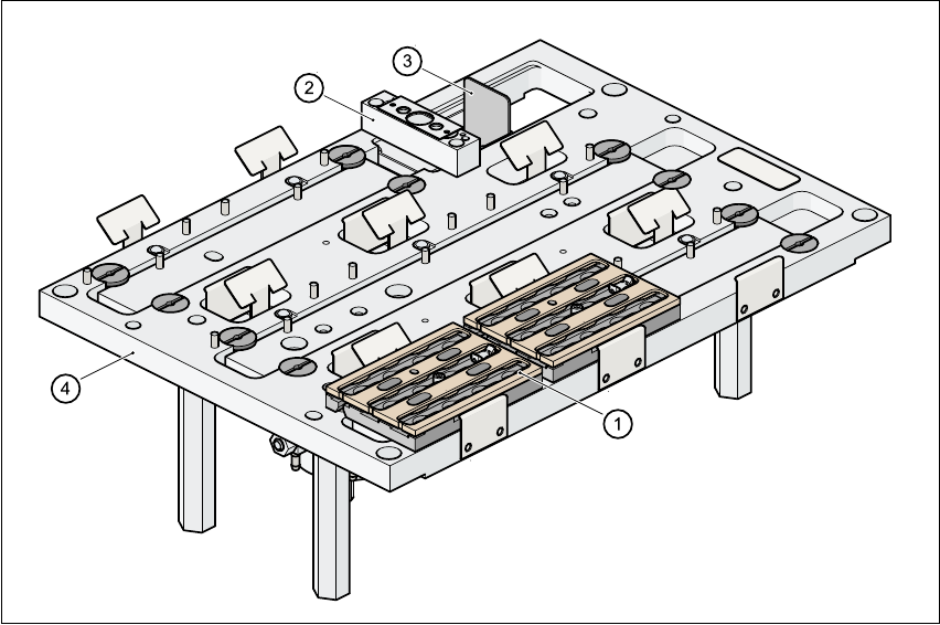
Fig. 5.1 - 1 Nozzle changer for the 12-segment collect&place head, overview
5
(1) Magazine
(2) Nozzle discarding device
(3) Container for discarded nozzles
(4) Nozzle changer base