00192405-02.pdf - 第175页
User Manual SIPLAC E S-25 HM 5 Station extensions Software Vers ion SR.502.xx 01/2001 US Edition 5.5 Ceramic substrate ce ntering 175 5.5.4 T echnical dat a 5.5.5 Optical centering with oblique lighting 5.5.5.1 Gener al …
5 Station extensions User Manual SIPLACE S-25 HM
5.5 Ceramic substrate centering Software Version SR.502.xx 01/2001 US Edition
174
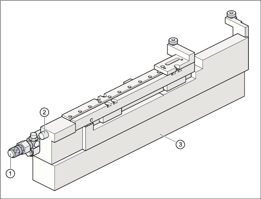
Fig. 5.5 - 2 Ceramic substrate centering (side view)
(1) Connecting nozzle
(2) ‘Ceramic substrate centering’ sensor
(3) Base
5.5.3.3 Maintenance
– Clean and grease the ball race in the X-axis centering unit.
– If necessary, check that the pneumatic driving mechanism is running smoothly.
– The conveyor should be maintained as described in the maintenance instructions.
User Manual SIPLACE S-25 HM 5 Station extensions
Software Version SR.502.xx 01/2001 US Edition 5.5 Ceramic substrate centering
175
5.5.4 Technical data
5.5.5 Optical centering with oblique lighting
5.5.5.1 General
For optical centering, the special features of the ceramic substrate must be taken into account.
The contrast depends very much on the paste used for the adjustment structure, the clear area
surrounding the adjustment structure, and the type of illumination. 5
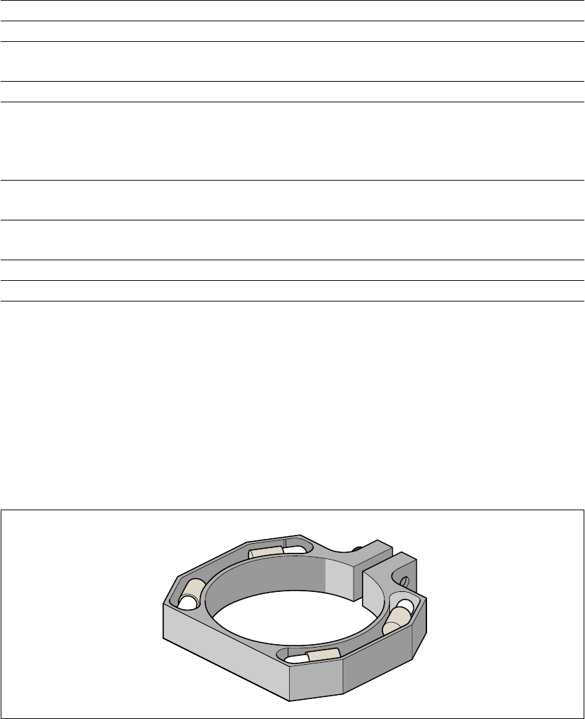
The oblique lighting unit is located on the front part of the sub-gantry camera. 5
Fig. 5.5 - 3 Oblique lighting unit for the sub-gantry camera
5
5
Substrate format 50 mm x 50 mm to 100 mm x 180 mm
Substrate thickness 0.5 mm to 1.5 mm
Substrate model unscribed (without problems)
scribed (requires testing)
Support on the conveyor 2.5 mm
Optical centering: field of view of the PCB vision module
Type of illumination for light pastes:
Type of illumination for dark pastes and close spacing to
adjacent structures (> 1 mm)
5.7 mm x 5.7 mm
PCB vision module (standard)
Oblique lighting (option)
Fiducial criteria See PCB vision module position recog-
nition
Mechanical centering:
X/Y centering accuracy ± 0.07 mm / 4 sigma
PCB underside clearance 12 mm
Compressed air connection 5.5 bar
5 Station extensions User Manual SIPLACE S-25 HM
5.5 Ceramic substrate centering Software Version SR.502.xx 01/2001 US Edition
176
Oblique lighting may be switched on instead of the existing lighting (see table in Section 5.5.2
on
page 172
). 5
PLEASE NOTE
Oblique lighting can only be used on the “sub-gantry camera”. 5
5.5.5.2 Fiducial mark recommendation for ceramic substrates
The contrast between the carrier package material and the circuit-board conductor layer is gener-
ally very small with ceramic substrates. The fiducials must therefore be selected with regard to
certain criteria concerning the fiducial shape and structure. Recommended fiducial shapes and
structures are given below. 5
Fiducial shape 5
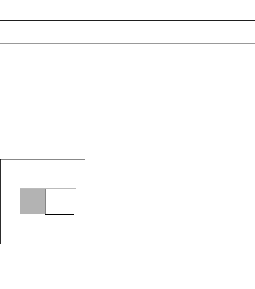
We recommend a rectangle or square with an edge length of > 1 mm, and a clearance
of > 0.5 mm. 5
5
Fig. 5.5 - 4 Recommended fiducial shape
PLEASE NOTE
Single crosses are also suitable, but they take up more space. 5
0.5 mm
1.0 mm