Pneumatic Tape Feeder _ENG Ver9_.pdf - 第32页
Samsung Pneumatic T ape Feeder Users' Manual 2-8 Figur e 2-12. Setting the tape r eel of the 8mm non-stop tape feeder Figur e 2-13. Setting the tape r eel of the 12-56mm tape feeder Figur e 2-14. T ape r eel setting…
Operation of the Tape Feeder
2-7
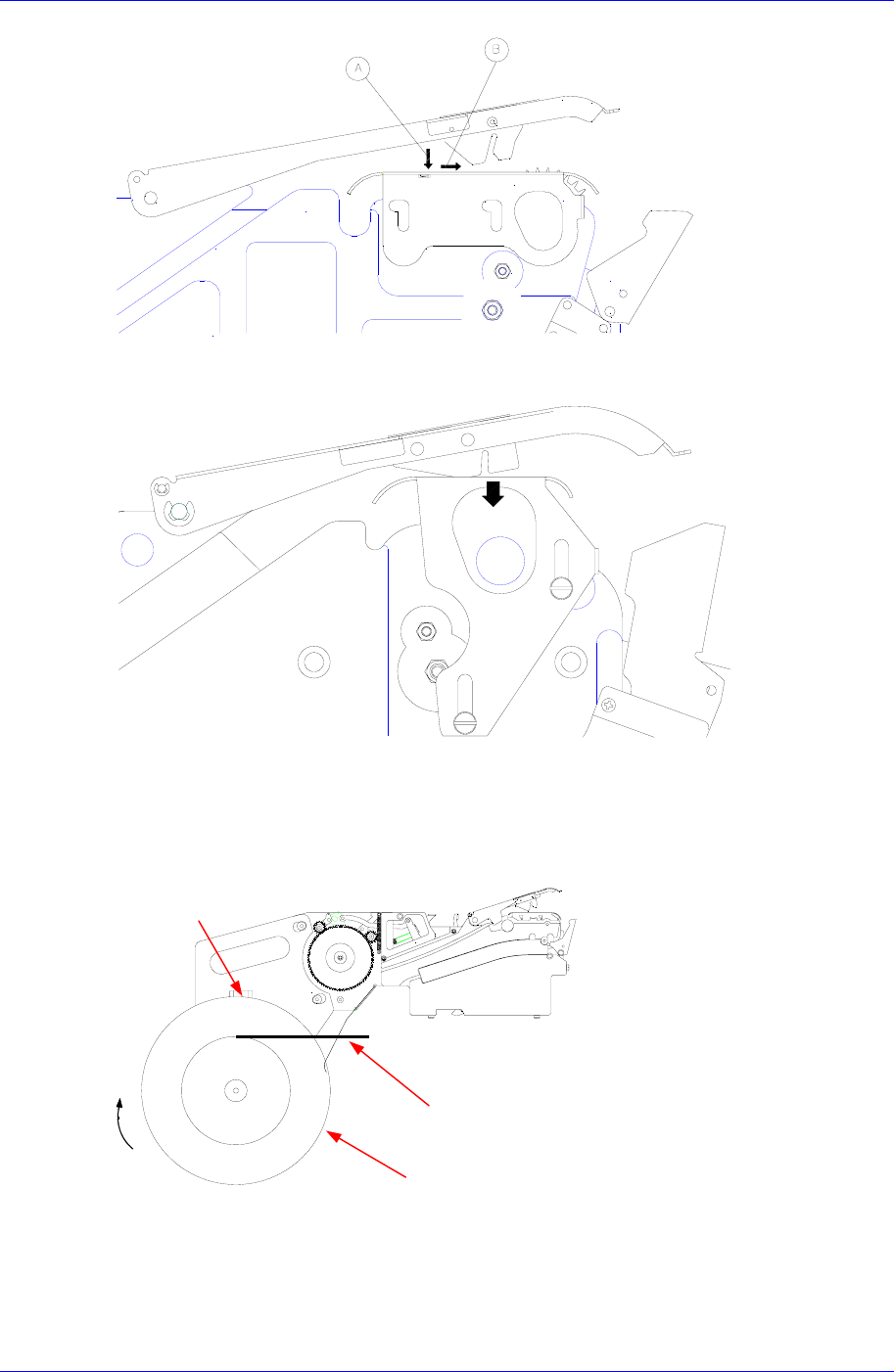
Figure 2-9. Locking the buck-up of the 12mm tape feeder
Figure 2-10. Locking the buck-up of the 16-56mm tape feeder
Taking note of the direction for winding the tape, set the tape reel as shown in the figure
below.
Figure 2-11. Setting the tape reel of the 8mm tape feeder
Tape
Tape reel locke
r
Tape reel
Direction
of rotation
Samsung Pneumatic Tape Feeder Users' Manual
2-8
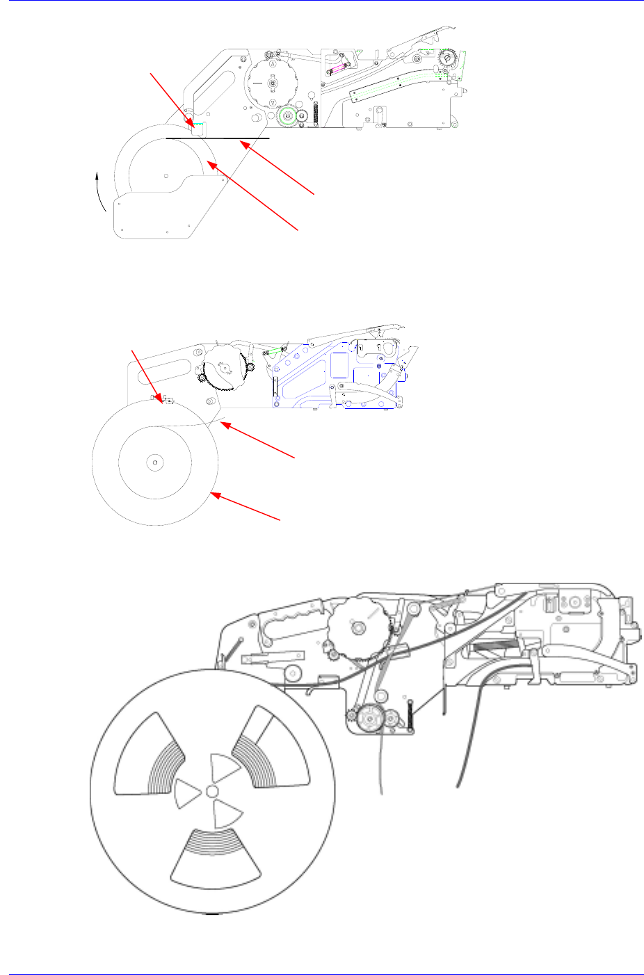
Figure 2-12. Setting the tape reel of the 8mm non-stop tape feeder
Figure 2-13. Setting the tape reel of the 12-56mm tape feeder
Figure 2-14. Tape reel setting for the 12mm-56mm Non-Stop Tape Feeder
Tape
Tape brake
Tape reel
Tape brake
Tape
Tape reel
Operation of the Tape Feeder
2-9
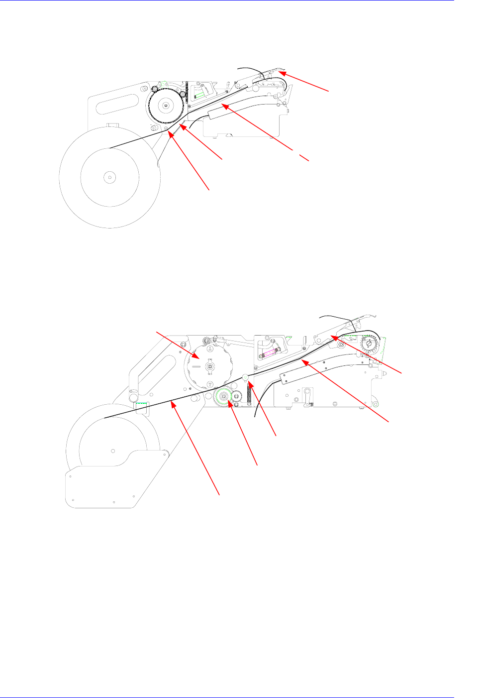
Pass the tape through groove A as shown in the figure below.
Figure 2-15. Installing path of the tape
For the 8mm Non-Stop tape feeder, pass the tape between the drain gear and idler, over
the side roller, and through groove A.
Figure 2-16. Mounting path of the tape (8mm non-stop tape feeder)
The tape consists of three parts, the upper cover tape, the carrier tape, and the bottom
cover tape. In general, the carrier tape and the upper cover tape are not separated, so
together they are called the carrier tape.
Tape guide
Groove A
Tape
Side roller
Groove A
Tape guide
Tape
Drain gea
r
Idler gear
Side roller