Pneumatic Tape Feeder _ENG Ver9_.pdf - 第40页
Samsung Pneumatic T ape Feeder Users' Manual 2-16 For the 8mm tape feeder , pass the upper cover ta pe coming out of the tape separation slit through groove B by keeping in contact with rollers A, B, and C. Figur e …
Operation of the Tape Feeder
2-15
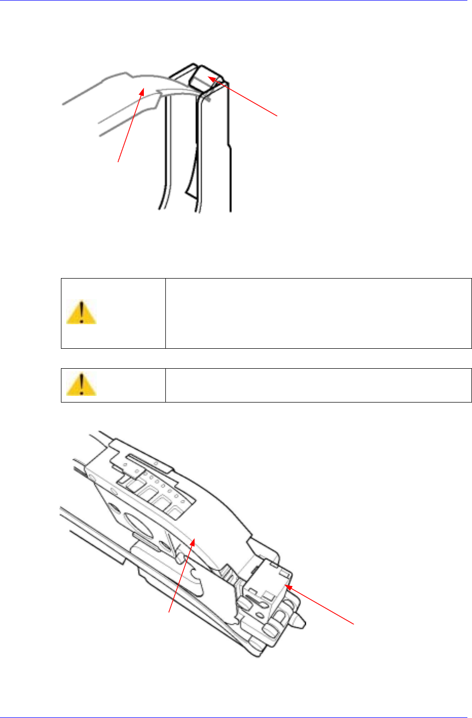
When using the 8mm Non-Stop tape feeder or the 0603 disposal type tape feeder, ensure
that the tape guide and the lock cover are properly locked.
Figure 2-27.Checking the locking state of the tape guide and the lock cover (8mm non-stop tape
feeder, 0603 disposal type tape feeder)
Figure 2-28. Checking the locking state of the tape guide and the lock cover (12mm~56mm non-
stop tape feeder)
Caution
Check the locking state of the tape guide and the lock
cover. The tape feeder whose tape guide and lock cover
are not properly locked may cause problems such as lack
of tape supply or collision with the machine. Ensure that
they are properly locked prior to use.
Caution
Check if the sprocket is engaged in the tape hole.
Tape guide
Lock cover
Tape guide
Lock cover
Samsung Pneumatic Tape Feeder Users' Manual
2-16
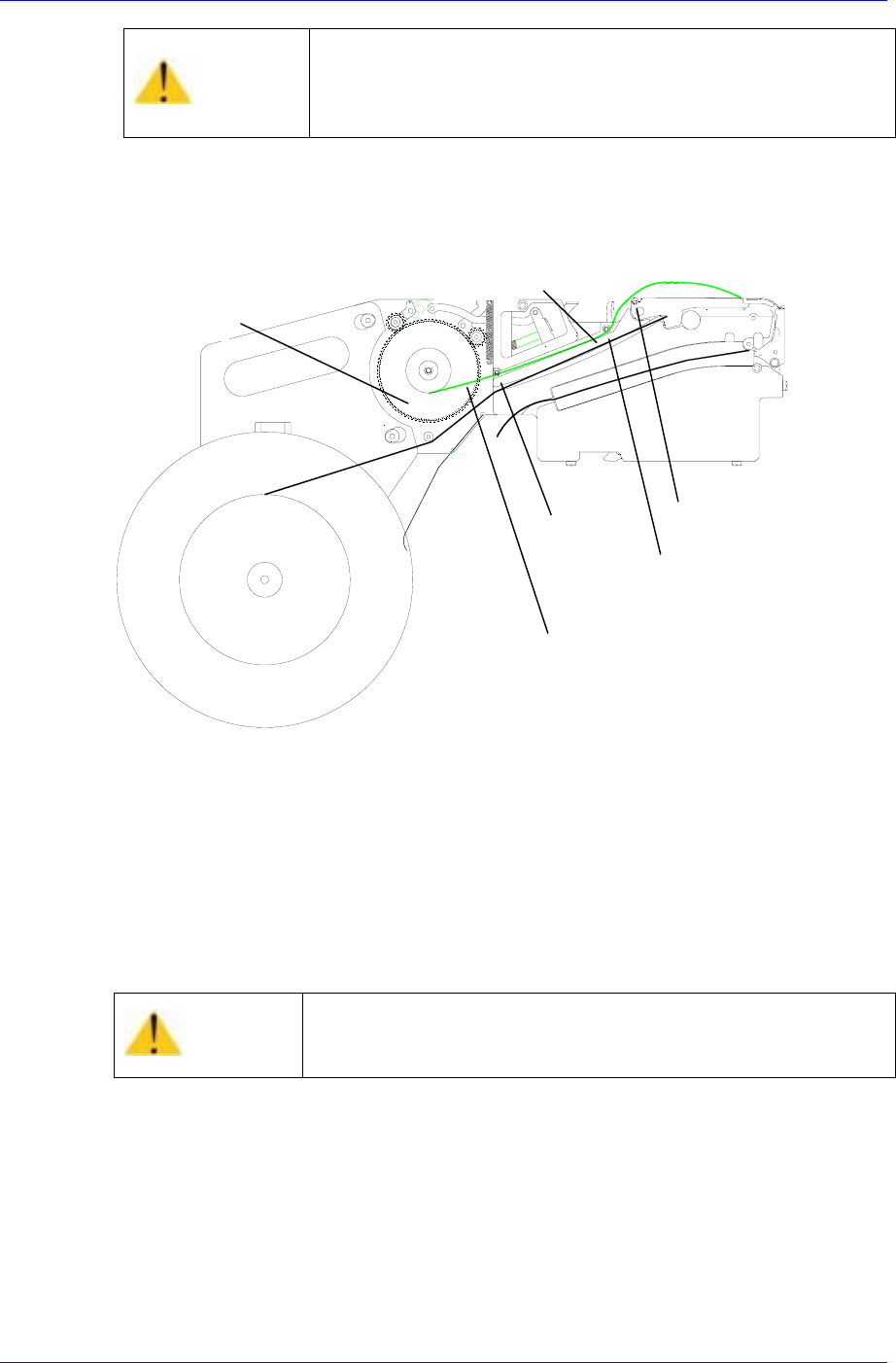
For the 8mm tape feeder, pass the upper cover tape coming out of the tape separation slit
through groove B by keeping in contact with rollers A, B, and C.
Figure 2-29. Installing the upper cover tape of the 8mm tape feeder
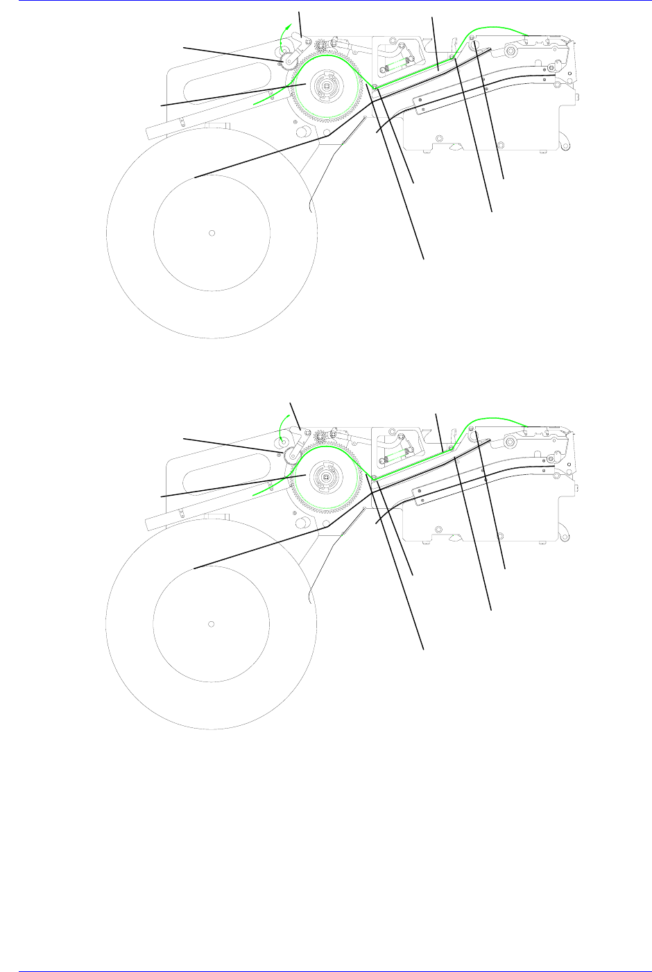
For the 8mm disposal type tape feeder, wind the end of the upper cover tape that has
passed through groove B on the upper of the drain gear as shown in the figure below.
Then pull the drain pawl clockwise so that the end of the upper cover tape is between the
drain gear and forming gear, Release the drain pawl to fix the end of the upper cover tape.
Caution
Since errors (no tape feed or collision with the machine
body) can occur if the tape feeder is used with the tape
guide and locking cover being incompletely locked, ensure
that the tape feeder is completely locked before using it.
Caution
When the cover tape is fixed, be careful so that fingers don’t
get stuck between the forming gear and the drain gear as
the drain pawl receives force from the spring.
Roller A
Roller B
Roller C
Upper cover tape
Take up reel
Groove B
Operation of the Tape Feeder
2-17
Figure 2-30. Installing the upper cover tape of the 8mm disposal type tape feeder (drain gear)
Figure 2-31. Installing the upper cover tape of the 8mm disposal type tape feeder (forming gear)
For the 8mm disposal type tape feeder, fix the end of the upper cover tape that has passed
through groove B and then it is between the drain gear and the forming gear. And rotate
the drain gear counterclockwise until there is no slack in the tape as shown in the figure
below.
Forming gea
r
Groove B
The upper of the drain gea
r
Drain pawl
Forming gea
r
Groove B
The upper of the drain gear
Drain pawl
Upper cover tape
Roller C
Roller B
Roller A
Upper cover tape
Roller C
Roller B
Roller A