Pneumatic Tape Feeder _ENG Ver9_.pdf - 第34页
Samsung Pneumatic T ape Feeder Users' Manual 2-10 Figur e 2-17. Composition of the tape Strip of f about 30cm of the upper cover tape from the end, and pass it through the tape slit as shown in the figure below . Fi…
Operation of the Tape Feeder
2-9
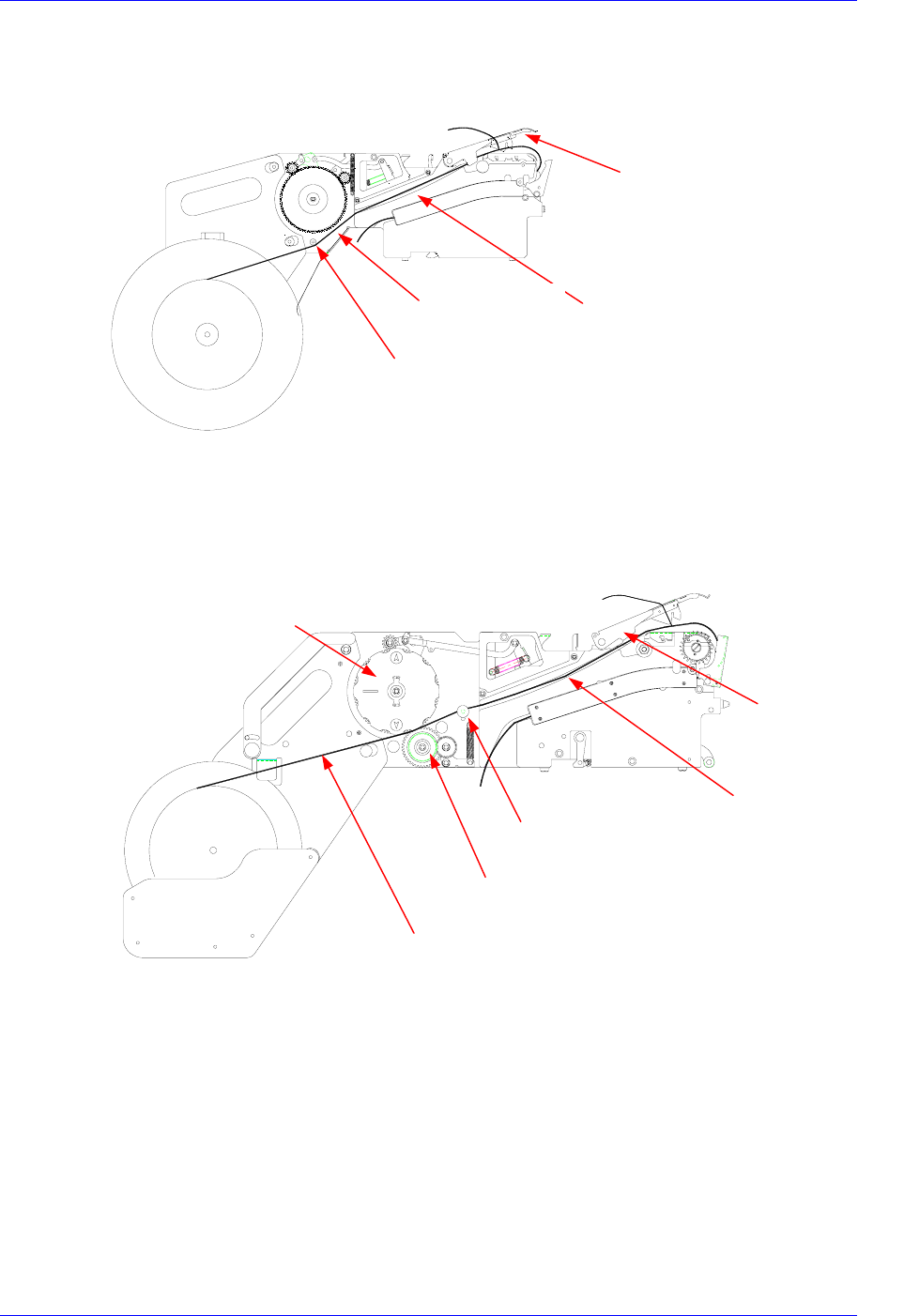
Pass the tape through groove A as shown in the figure below.
Figure 2-15. Installing path of the tape
For the 8mm Non-Stop tape feeder, pass the tape between the drain gear and idler, over
the side roller, and through groove A.
Figure 2-16. Mounting path of the tape (8mm non-stop tape feeder)
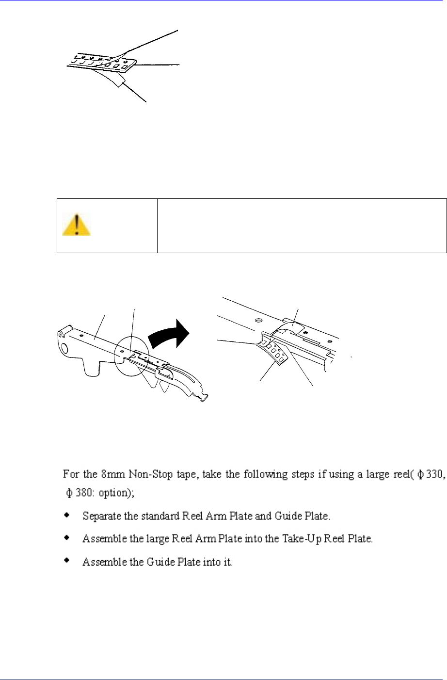
The tape consists of three parts, the upper cover tape, the carrier tape, and the bottom
cover tape. In general, the carrier tape and the upper cover tape are not separated, so
together they are called the carrier tape.
Tape guide
Groove A
Tape
Side roller
Groove A
Tape guide
Tape
Drain gea
r
Idler gear
Side roller
Samsung Pneumatic Tape Feeder Users' Manual
2-10
Figure 2-17. Composition of the tape
Strip off about 30cm of the upper cover tape from the end, and pass it through the tape slit
as shown in the figure below.
Figure 2-18. Exit of the upper cover tape
Caution
If the distance from the end of the carrier tape to the pickup
position is too short, the tape may get caught or other
problems may occur. Ensure that this distance is sufficient
in length.
Top cover tape
Carrier tape
Bottom cover tape
Tape separation slit
Tape guide
Upper cover tape
Cover tape
Upper cover tape
Operation of the Tape Feeder
2-11
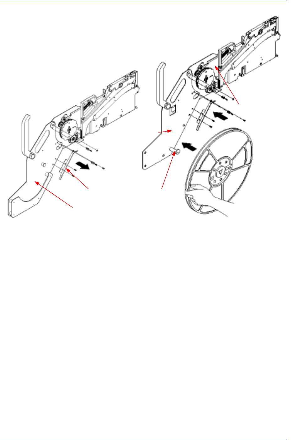
Figure 2-19. Replacing a large reel (8mm Non-Stop tape feeder)
Take-up reel plate
Large reel arm plate
Standard reel arm plate
Reel
hange
r
Guide plate