SMW200A_specs_en_3606-8037-22_v2700.pdf - 第13页
Version 27.00, October 2024 Rohde & Schwar z R&S ® SMW200A Vec tor Signal Generator 13 In NARROW mode , the reference PLL acts as a clean- up - loop in which the phase noise is mainly determined by the signal gen…
Version 27.00, October 2024
12 Rohde & Schwarz R&S
®
SMW200A Vector Signal Generator
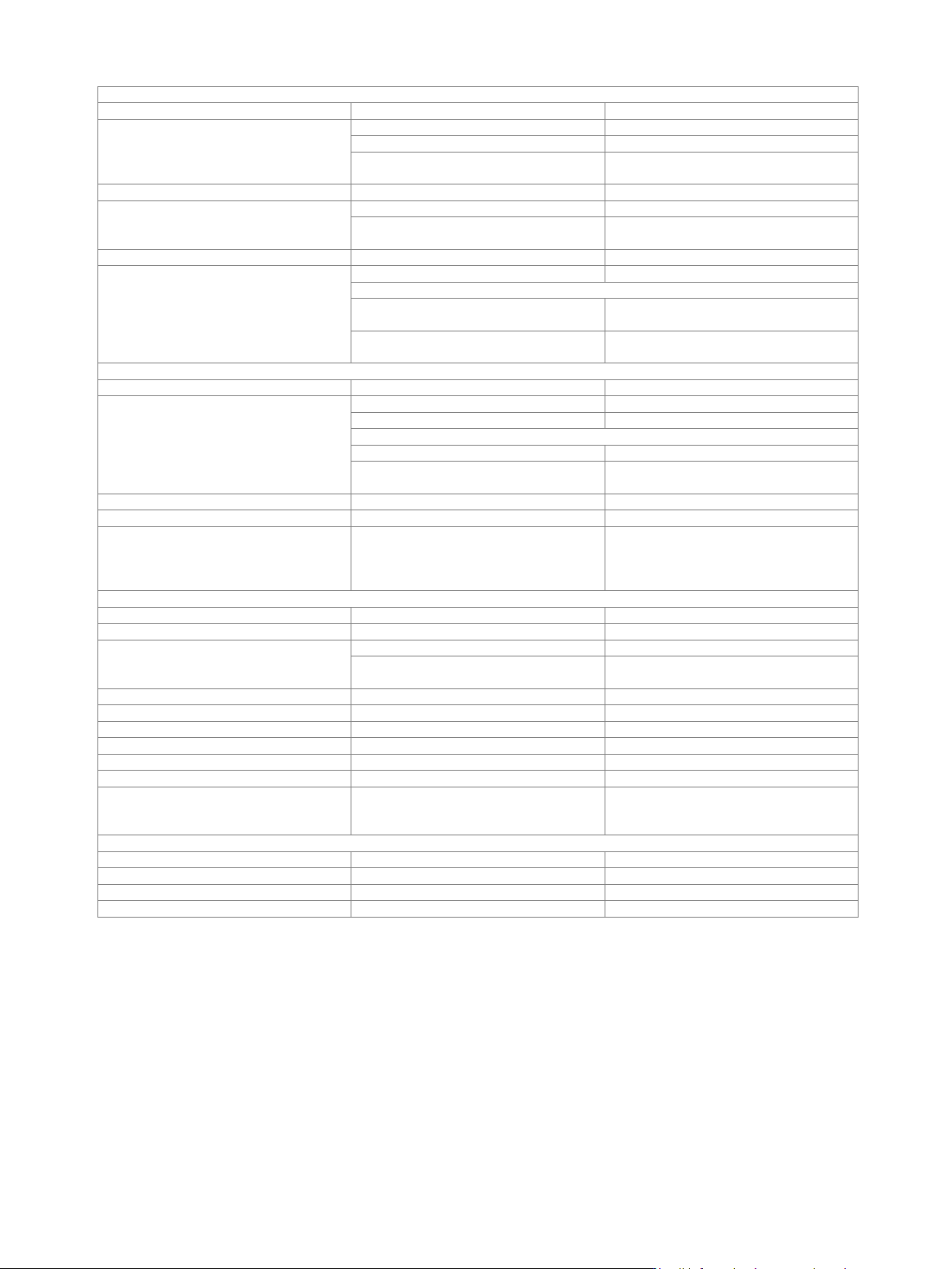
Input for external reference frequency
Connector type
REF in on rear panel
BNC female
Input frequency
standard
10 MHz
with R&S
®
SMW-K703 option
10 MHz, 100 MHz
with R&S
®
SMW-K704 option
10 MHz,
1 MHz to 100 MHz, variable
Input frequency setting resolution
with R&S
®
SMW-K704 option
0.1 Hz
Input level range
level limits
0 dBm to 20 dBm
recommended input level for optimum
phase noise performance
7 dBm to 13 dBm
Input impedance
50 Ω (nom.)
Minimum frequency locking range
synchronization bandwidth: wide
±3 · 10
–6
synchronization bandwidth: narrow
standard or with R&S
®
SMW-B709
option
±0.3 · 10
–6
with R&S
®
SMW-B710 or
R&S
®
SMW-B711 option
±0.15 · 10
–6
Output for internal reference frequency
Connector type
REF OUT on rear panel
BNC female
Output frequency
standard
sine wave 10 MHz
with R&S
®
SMW-K703 option
sine wave 10 MHz, 100 MHz
with R&S
®
SMW-K704 option
instrument set to internal reference
sine wave 10 MHz
instrument set to external reference
sine wave 10 MHz,
applied external reference frequency
Output level
7 dBm to 14 dBm
Source impedance
50 Ω (nom.)
Wideband noise
with R&S
®
SMW-K703 option,
100 MHz, internal reference,
carrier offset = 10 MHz,
measurement bandwidth = 1 Hz
< –155 dBc, –159 dBc (typ.)
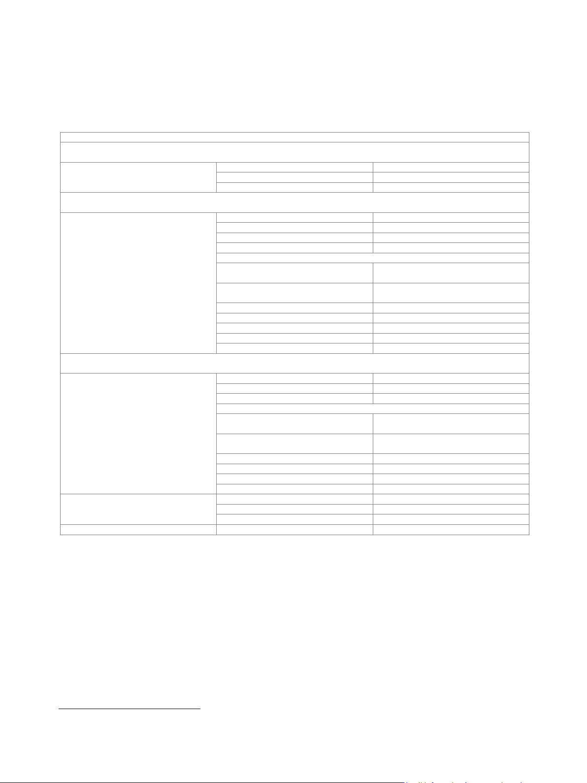
Ultra low noise 1 GHz reference frequency (R&S
®
SMW-K703 option)
Input connector type
1 GHz in on rear panel
SMA female
Input frequency
1 GHz
Input level range
level limits
≥ 6 dBm, ≤ 20 dBm
recommended input level for optimum
phase noise performance
7 dBm to 13 dBm
Input impedance
50 Ω (nom.)
Minimum frequency locking range
±3 · 10
–6
Output connector type
1 GHz out on rear panel
SMA female
Output frequency
sine wave 1 GHz
Output level
7 dBm to 14 dBm
Source impedance
50 Ω (nom.)
Wideband noise
1 GHz, internal reference,
carrier offset = 10 MHz,
measurement bandwidth = 1 Hz
< –154 dBc, –158 dBc (typ.)
Input for electronic tuning of internal reference frequency
Connector type
EFC on rear panel
BNC female
Sensitivity
external tuning slope
1 · 10
–8
/V (typ.)
Input voltage
–10 V to +10 V
Input impedance
10 kΩ (nom.)
R&S
®
SMW-K703 option (100 MHz, 1 GHz reference input/output)
When this option is installed, the 1 GHz low noise input and output for synchronization can be used.
In WIDE mode, the signal generator will use this signal directly as a reference for the synthesizer.
This option should be used if a very high phase stability between multiple generators is required.
The 100 MHz low noise input and output mode is only available with this option.
R&S
®
SMW-K704 option (flexible reference input)
When this option is installed, the reference input frequency can be set in 0.1 Hz steps from 1.0 MHz to 100 MHz.
The signal generator will lock its internal reference oscillator on the input frequency.
Note on choosing the proper reference synchronization bandwidth.
The user has the choice to set the synchronization bandwidth either to NARROW or WIDE.
In WIDE mode, the best possible phase stability is achieved.
The phase noise performance close to the carrier depends on the phase noise of the external signal source.
Version 27.00, October 2024
Rohde & Schwarz R&S
®
SMW200A Vector Signal Generator 13
In NARROW mode, the reference PLL acts as a clean-up-loop in which the phase noise is mainly determined by the signal generator’s
internal reference source.
This mode is recommended when using external reference sources with close-to-carrier phase noise worse than the R&S
®
SMW200A
(i. e. rubidium standards).
Note that due to the slow synchronization, reference locking can take up to 10 s.
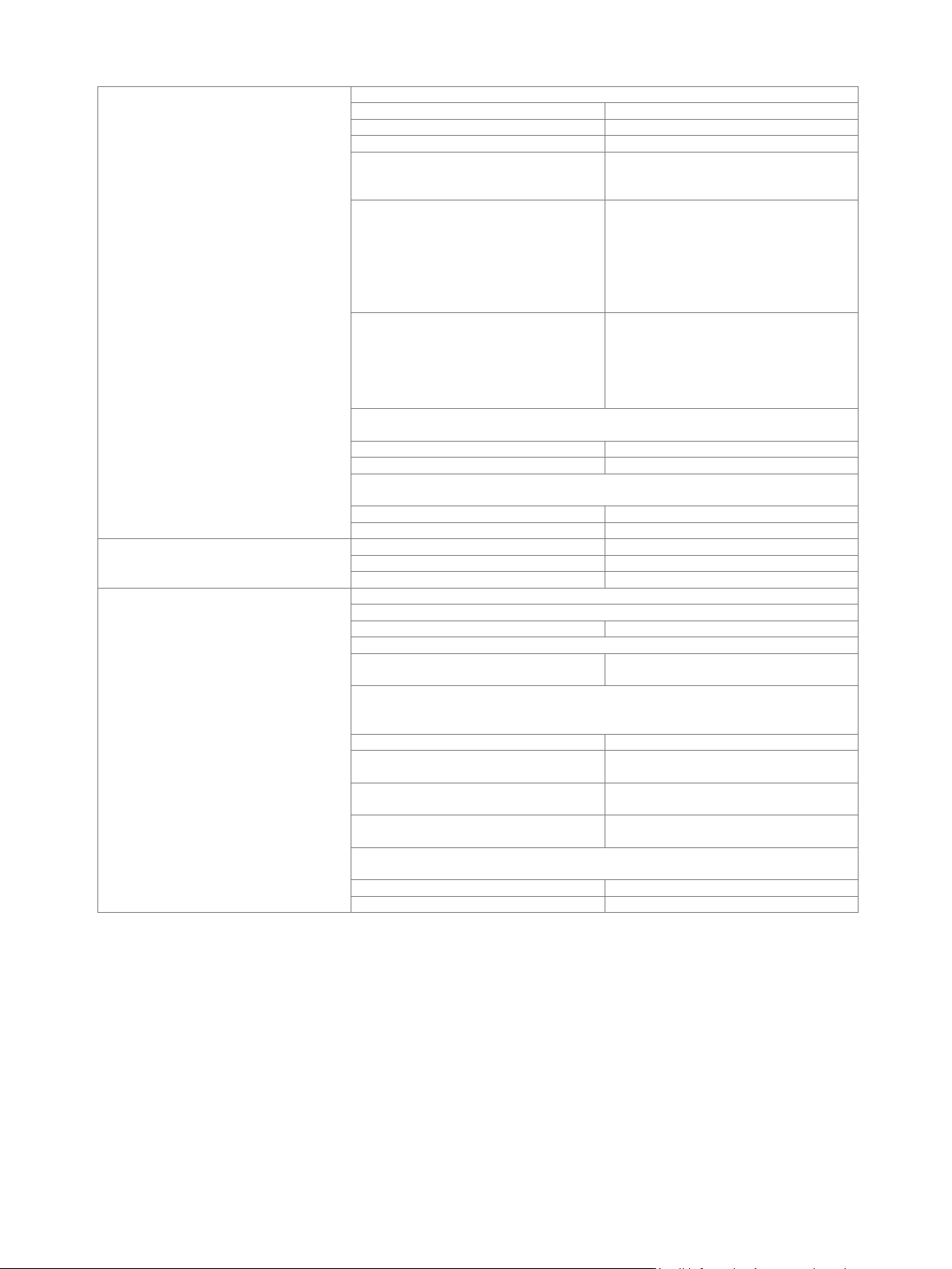
Level
Specified level range
With R&S
®
SMW-B1003, R&S
®
SMW-B2003, R&S
®
SMW-B1006, R&S
®
SMW-B2006, R&S
®
SMW-B1007, R&S
®
SMW-B2007,
R&S
®
SMW-B1012, R&S
®
SMW-B2012, R&S
®
SMW-B1020, R&S
®
SMW-B2020 frequency options
100 kHz ≤ f < 1 MHz
–120 dBm to +3 dBm (PEP)
2
1 MHz ≤ f ≤ 3 MHz
–120 dBm to +8 dBm (PEP)
2
3 MHz < f ≤ 20 GHz
–120 dBm to +18 dBm (PEP)
2
With R&S
®
SMW-B1031, R&S
®
SMW-B2031, R&S
®
SMW-B1040, R&S
®
SMW-B1040N, R&S
®
SMW-B1044, R&S
®
SMW-B2044,
R&S
®
SMW-B1044N, R&S
®
SMW-B2044N, R&S
®
SMW-B1044O, R&S
®
SMW-B2044O frequency options
100 kHz ≤ f < 1 MHz
–120 dBm to +3 dBm (PEP)
2
1 MHz ≤ f ≤ 3 MHz
–120 dBm to +8 dBm (PEP)
2
3 MHz < f ≤ 3 GHz
–120 dBm to +18 dBm (PEP)
2
3 GHz < f ≤ 14 GHz
–120 dBm to +17 dBm (PEP)
2
14 GHz < f ≤ 20 GHz
CW, I/Q modulation,
signal bandwidth ≤ 160 MHz
–120 dBm to +15 dBm (PEP)
2
I/Q modulation,
signal bandwidth > 160 MHz
–120 dBm to +12 dBm (PEP)
2
20 GHz < f ≤ 29 GHz
–120 dBm to +18 dBm (PEP)
2
29 GHz < f ≤ 33 GHz
–120 dBm to +17 dBm (PEP)
2
33 GHz < f ≤ 40 GHz
–120 dBm to +15 dBm (PEP)
2
40 GHz < f ≤ 42 GHz
–120 dBm to +13 dBm (PEP)
2
42 GHz < f ≤ 44 GHz
–120 dBm to +12 dBm (PEP)
2
With R&S
®
SMW-B1056, R&S
®
SMW-B1056N, R&S
®
SMW-B1056O, R&S
®
SMW-B1067, R&S
®
SMW-B1067N, R&S
®
SMW-B1067O
frequency options
100 kHz ≤ f < 1 MHz
–120 dBm to +3 dBm (PEP)
2
1 MHz ≤ f ≤ 3 MHz
–120 dBm to +8 dBm (PEP)
2
3 MHz < f ≤ 16 GHz
–120 dBm to +15 dBm (PEP)
2
16 GHz < f ≤ 20 GHz
CW, I/Q modulation,
signal bandwidth ≤ 160 MHz
–120 dBm to +13 dBm (PEP)
2
I/Q modulation,
signal bandwidth > 160 MHz
–120 dBm to +10 dBm (PEP)
2
20 GHz < f ≤ 33 GHz
–120 dBm to +15 dBm (PEP)
2
33 GHz < f ≤ 43 GHz
–115 dBm to +10 dBm (PEP)
2
43 GHz < f ≤ 60 GHz
–115 dBm to +12 dBm (PEP)
2
60 GHz < f ≤ 67 GHz
–115 dBm to +10 dBm (PEP)
2
Setting range
100 kHz ≤ f < 1 MHz
–145 dBm to +8 dBm
1 MHz ≤ f < 3 MHz
–145 dBm to +13 dBm
3 MHz ≤ f ≤ 67 GHz
–145 dBm to +30 dBm
Resolution of setting
0.01 dB (nom.)
2
PEP = peak envelope power.
Version 27.00, October 2024
14 Rohde & Schwarz R&S
®
SMW200A Vector Signal Generator
Level error
level setting characteristic: auto, temperature range from +18 °C to +33 °C
100 kHz ≤ f ≤ 3 GHz
< 0.5 dB
3 GHz < f ≤ 6 GHz
< 0.7 dB
6 GHz < f ≤ 20 GHz
< 0.9 dB
R&S
®
SMW-B1031, R&S
®
SMW-B2031,
R&S
®
SMW-B1040, R&S
®
SMW-B1040N,
20 GHz < f ≤ 40 GHz
< 1.1 dB
R&S
®
SMW-B1044,
R&S
®
SMW-B2044,
R&S
®
SMW-B1044N,
R&S
®
SMW-B2044N,
R&S
®
SMW-B1044O,
R&S
®
SMW-B2044O,
20 GHz < f ≤ 44 GHz
< 1.2 dB
R&S
®
SMW-B1056,
R&S
®
SMW-B1056N,
R&S
®
SMW-B1056O,
R&S
®
SMW-B1067, R&S
®
SMW-B1067N,
R&S
®
SMW-B1067O,
20 GHz < f ≤ 43 GHz
< 1.1 dB
R&S
®
SMW-B1056, R&S
®
SMW-B1056N, R&S
®
SMW-B1056O,
43 GHz < f ≤ 56 GHz
level ≥ –90 dBm
< 1.2 dB
level < –90 dBm
< 1.5 dB
R&S
®
SMW-B1067, R&S
®
SMW-B1067N, R&S
®
SMW-B1067O,
43 GHz < f ≤ 67 GHz
level ≥ –90 dBm
< 1.2 dB
level < –90 dBm
< 1.5 dB
Additional level error
I/Q modulation
optimization mode: high quality, fast
< 0.3 dB
pulse modulation
< 0.5 dB
Output impedance, VSWR in 50 Ω system
ALC state: on
R&S
®
SMW-B1003, R&S
®
SMW-B2003, R&S
®
SMW-B1006, R&S
®
SMW-B2006
100 kHz < f ≤ 6 GHz
< 1.9, < 1.5 (typ.)
R&S
®
SMW-B1007, R&S
®
SMW-B2007, R&S
®
SMW-B1012, R&S
®
SMW-B2012,
100 kHz < f ≤ 12.75 GHz
< 2.0, < 1.6 (typ.)
R&S
®
SMW-B1020, R&S
®
SMW-B2020, R&S
®
SMW-B1031, R&S
®
SMW-B2031,
R&S
®
SMW-B1040, R&S
®
SMW-B1040N, R&S
®
SMW-B1044, R&S
®
SMW-B2044,
R&S
®
SMW-B1044N, R&S
®
SMW-B2044N, R&S
®
SMW-B1044O, R&S
®
SMW-B2044O
100 kHz < f ≤ 20 GHz
< 2.1, < 1.7 (typ.)
step attenuator = 0 dB,
20 GHz < f ≤ 38 GHz
< 2.2, < 1.8 (typ.)
step attenuator = 0 dB,
38 GHz < f ≤ 44 GHz
< 2.6, < 2.2 (typ.)
step attenuator ≥ 5 dB,
20 GHz < f ≤ 44 GHz
< 2.1, < 1.7 (typ.)
R&S
®
SMW-B1056, R&S
®
SMW-B1056N, R&S
®
SMW-B1056O,
R&S
®
SMW-B1067, R&S
®
SMW-B1067N, R&S
®
SMW-B1067O
100 kHz < f ≤ 38 GHz
< 2.2, < 1.8 (typ.)
38 GHz < f ≤ 50 GHz
< 2.6, < 2.2 (typ.)