SMW200A_specs_en_3606-8037-22_v2700.pdf - 第44页
Version 27.00, October 2024 44 Rohde & Schwar z R&S ® SMW200A Vec tor Signal Generator 2 × R&S ® SMW-B10 + 4 × R&S ® SMW-B14 + R&S ® SMW-B13T + 2 × R&S ® SMW-K18 depends on selec ted system confi …
Version 27.00, October 2024
Rohde & Schwarz R&S
®
SMW200A Vector Signal Generator 43
Digital baseband inputs/outputs
Depending on the installed software and hardware options, the R&S
®
SMW200A is able to receive digital baseband signals and to
output digital baseband signals. The digital I/Q input/output can be used for the lossless connection of the R&S
®
SMW200A to the
digital I/Q input/output of other Rohde & Schwarz instruments (for example the CMW500 wideband radio communication tester in
fading applications).
Digital baseband outputs: At least one R&S
®
SMW-K18 option must be installed. This option can be installed once if the instrument is
equipped with the R&S
®
SMW-B13 option. If the instrument is equipped with the R&S
®
SMW-B13T option, digital baseband outputs can
be used either on signal path A or B with one R&S
®
SMW-K18 option. For digital baseband outputs to be used on signal paths A and B
simultaneously, two R&S
®
SMW-K18 must be installed. Furthermore, to enable two or more digital baseband outputs in MIMO modes,
two R&S
®
SMW-K18 must be installed.
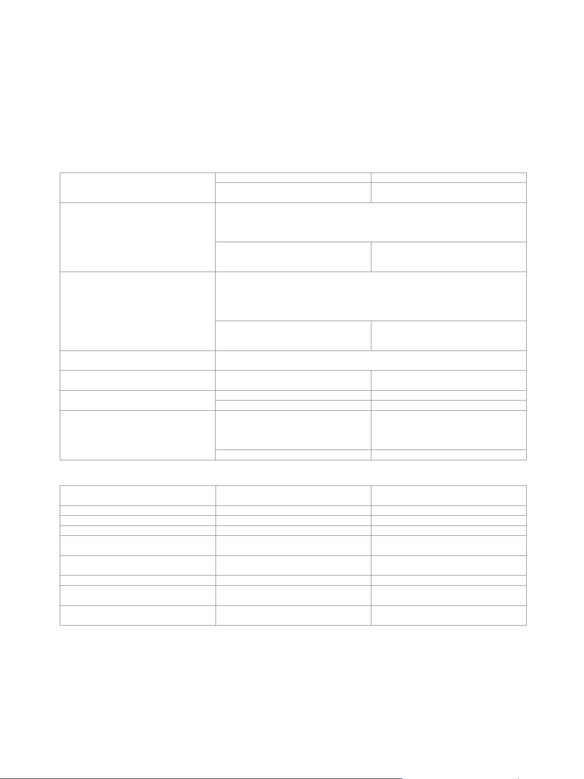
Signal outputs
analog and digital, digital only
with 2 × R&S
®
SMW-K18 installed
analog and digital, digital only, digital only
multiplexed
Digital only
The streams are output via the digital I/Q outputs only; analog I/Q outputs are not
available. External modulation signals can be output via the RF outputs (I/Q modulation
mode: external wideband I/Q).
Note: System configurations with more than 4 streams are not available in this mode.
with R&S
®
SMW-K551 installed
The instrument runs at reduced speed
depending on the device connected to the
digital I/Q output (slow I/Q).
Digital only multiplexed
The streams are output via BBMM1 and BBMM2 in multiplexed mode, i.e. up to 4
streams are output via a single digital output. Analog I/Q outputs are not available.
External modulation signals can be output via the RF outputs (I/Q modulation mode:
external wideband I/Q).
Note: All system configurations available on the instrument are available in this mode.
with R&S
®
SMW-K551 installed
The instrument runs at reduced speed
depending on the device connected to the
digital I/Q output (slow I/Q).
Analog and digital
The instrument runs in regular operating mode, both analog and digital outputs are
available, slow I/Q is not possible.
Number of digital outputs
according to selected system configuration
(see table below)
Number of streams per digital output
digital only
1
digital only multiplexed
1 to 4
Bandwidth
general
according to selected system configuration
(see section Multichannel, MIMO, fading
and noise, specifications for
R&S
®
SMW-K74, -K75, -K76 options)
4 streams mapped to one digital output
40 MHz
The following table gives an overview of which software and hardware options are required for which digital I/Q connectivity:
Minimum required R&S
®
SMW200A
options
Digital I/Q inputs
Digital I/Q outputs
R&S
®
SMW-B13 + 1 × R&S
®
SMW-K18
–
1
R&S
®
SMW-B13T + 2 × R&S
®
SMW-K18
–
2
1 × R&S
®
SMW-B10
1
–
1 × R&S
®
SMW-B10 + R&S
®
SMW-B13 +
1 × R&S
®
SMW-K18
1
1
1 × R&S
®
SMW-B10 + R&S
®
SMW-B13T +
2 × R&S
®
SMW-K18
1
2
2 × R&S
®
SMW-B10
2
–
2 × R&S
®
SMW-B10 + R&S
®
SMW-B13 +
1 × R&S
®
SMW-K18
2
1
2 × R&S
®
SMW-B10 + R&S
®
SMW-B13T +
2 × R&S
®
SMW-K18
2
2
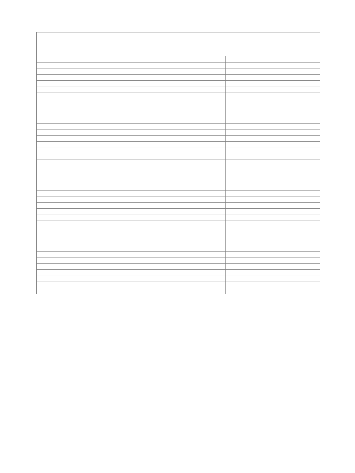
Version 27.00, October 2024
44 Rohde & Schwarz R&S
®
SMW200A Vector Signal Generator
2 × R&S
®
SMW-B10 + 4 × R&S
®
SMW-B14
+ R&S
®
SMW-B13T + 2 × R&S
®
SMW-K18
depends on selected system configuration
(for required additional options for specific system configurations, see section
Multichannel, MIMO, fading and noise, specifications for R&S
®
SMW-K74, -K75, -K76
options)
3x1
3
1
3x2
3
2
3x3
3
3
1x3
1
3
2x3
2
3
4x1
4
1
4x2
4
2
4x3
4
3
4x4
4
4
1x4
1
4
2x4
2
4
3x4
3
4
8x1
–
1
8x2
–
2
8x4
–
4
8x8
–
subset 1: 4,
subset 2: 4
1x8
1
6
2x8
2
6
4x8
2
6
3x1x1
3
3
4x1x1
4
4
5x1x1
–
3
6x1x1
–
4
7x1x1
–
5
8x1x1
–
6
2x1x2
2
4
2x2x1
4
2
2x2x2
4
4
2x1x3, 2x2x3
2
5
2x1x4, 2x2x4
2
6
2x3x1, 2x4x1
2
2
2x3x2, 2x4x2
2
4
2x3x3, 2x4x3
–
5
2x3x4, 2x4x4
–
6
3x2x1
2
3
3x1x2, 3x2x2
2
4
4x2x1
2
4
4x1x2, 4x2x2
2
6
Version 27.00, October 2024
Rohde & Schwarz R&S
®
SMW200A Vector Signal Generator 45
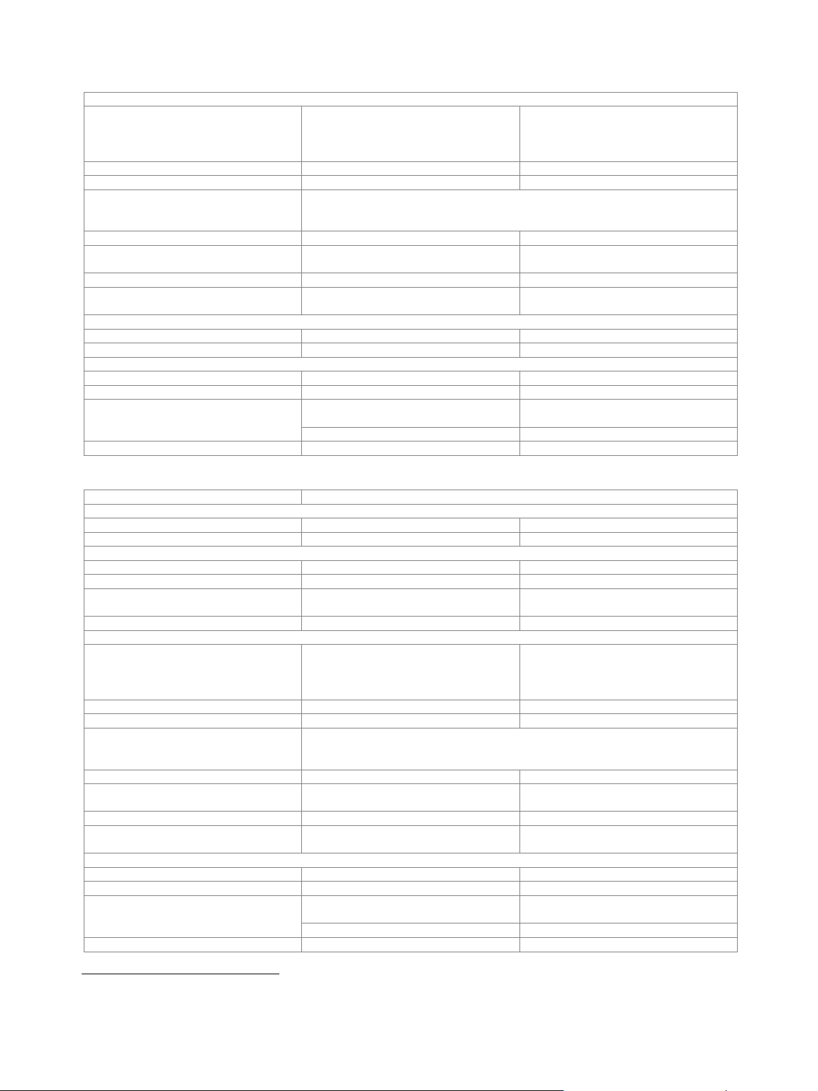
Output parameters
Interface
Standard
in line with R&S
®
Digital I/Q Interface
PAD-R
12
,
I/Q data and control signals, data and
interface clock
Level
LVDS
Connector
26-pin MDR
I/Q sample rate
With source "user-defined", the sample rate must be entered via the parameter "sample
rate", no I/Q data clock being necessary. With source "digital I/Q out", the sample rate
will be estimated on the basis of the applied I/Q data clock.
Source
user-defined, digital I/Q out
Sample rate
maximum sample rate depends on
connected receiving device
400 Hz to 200 MHz
Resolution (user-defined)
0.001 Hz
Frequency uncertainty
(user-defined)
< (5 · 10
−14
+ relative deviation of
reference frequency) · sample rate (nom.)
I/Q data
Resolution
up to 18 bit
Logic format
two’s complement
Physical signal level
Setting range
0 to –60 dBFS
Setting resolution
0.01 dBFS
Bandwidth (RF)
sample rate = 200 MHz
(no interpolation, user-defined)
160 MHz
sample rate < 200 MHz (interpolation)
0.8 · sample rate
Control signals
markers
3
Input parameters
Input level
peak level
Peak level
Setting range
–60 dB to +3 dB, referenced to full scale
Setting resolution
0.01 dB
Crest factor
Setting range
0 dB to +30 dB
Setting resolution
0.01 dB
Adjust level function
automatically determines peak level and
crest factor of input signal
I/Q swap
I and Q signals swapped
on/off
Interface
Standard
in line with R&S
®
Digital I/Q Interface
PAD-R
12
,
I/Q data and control signals, data and
interface clock
Level
LVDS
Connector
26-pin MDR
I/Q sample rate
With source "user-defined", the sample rate must be entered via the parameter "sample
rate", no I/Q data clock being necessary. With source "digital I/Q in", the sample rate
will be estimated on the basis of the applied I/Q data clock.
Source
user-defined, digital I/Q in
Sample rate
maximum sample rate depends on
connected transmitting device
400 Hz to 200 MHz
Resolution (user-defined)
0.001 Hz
Frequency uncertainty
(user-defined)
< (5 · 10
−14
+ relative deviation of
reference frequency) · sample rate (nom.)
I/Q data
Resolution
18 bit
Logic format
two’s complement
Bandwidth (RF)
sample rate = 200 MHz
(no interpolation, user-defined)
160 MHz
sample rate < 200 MHz (interpolation)
0.8 · sample rate
Control signals
markers
3
12
R&S
®
Digital I/Q Interface PAD-R is a Rohde & Schwarz internal company guideline for the transmission of digital I/Q data. It is supported by a wide
range of signal generators, signal analyzers and radio communication testers.