SMW200A_specs_en_3606-8037-22_v2700.pdf - 第77页
Version 27.00, October 2024 Rohde & Schwar z R&S ® SMW200A Vec tor Signal Generator 77 Health and utilizatio n monitoring service (HUM S) ( R&S ® SMW -K980 option) Interfaces protocols and in terfaces support…
Version 27.00, October 2024
76 Rohde & Schwarz R&S
®
SMW200A Vector Signal Generator
Custom digital modulation (R&S
®
SMW-B9/-B10 options, real-time mode)
Deviation error with 2FSK, 4FSK
deviation 0.2 to 0.7 · symbol rate
Gaussian filter with B × T = 0.2 to 0.7, f = 1 GHz
symbol rate up to 2 MHz
0.25 % (meas.)
symbol rate up to 10 MHz
0.75 % (meas.)
Phase error with MSK
Gaussian filter with B × T = 0.2 to 0.7, f = 1 GHz
bit rate up to 2 MHz
0.15° (meas.)
bit rate up to 10 MHz
0.3° (meas.)
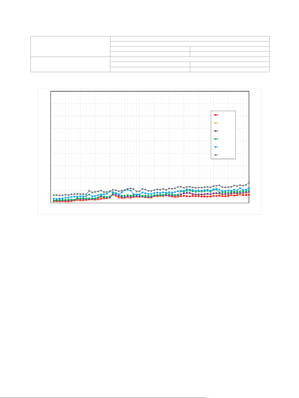
Measured EVM versus carrier frequency for 16QAM
0.0
0.5
1.0
1.5
2.0
2.5
3.0
3.5
4.0
4.5
0 5 10 15 20 25 30 35 40 45 50 55 60 65
EVM (rms) / %
Carrier Frequency / GHz
10 MSym/s
30 MSym/s
50 MSym/s
100 Msym/s
200 MSym/s
500 MSym/s
Version 27.00, October 2024
Rohde & Schwarz R&S
®
SMW200A Vector Signal Generator 77
Health and utilization monitoring service (HUMS)
(R&S
®
SMW-K980 option)
Interfaces
protocols and interfaces supported for
data readout and display
• SNMP (v1, v2c, v3)
• REST (JSON)
• SCPI
• device web
Services
information provided
• device information (model, serial
number, BIOS, date, time, system,
HUMS and software information)
• user-defined information tags
(e.g. for asset management)
• equipment information
(hardware, options, software, licenses)
• system operating status
• instrument security information
• service related information
(due dates etc.)
• mass storage related information
• instrument utilization data
• device history (event log)
Remote control
Interfaces
remote control
IEC 60625 (GPIB IEEE-488.2)
Ethernet/LAN
10/100/1000BASE-T
USB
3.0 (super speed)
serial
RS-232
22
Command set
SCPI 1999.5 or compatible command sets
IEC/IEEE bus address
0 to 30
Ethernet/LAN protocols and services
• VISA VXI-11 (remote control)
• Telnet/RawEthernet (remote control)
• VNC (remote operation with web
browser)
• FTP (file transfer protocol)
• SMB (mapping parts of the instrument
to a host file system)
Ethernet/LAN addressing
DHCP, static, support of ZeroConf and
M-DNS to facilitate direct connection to a
system controller
USB protocol
VISA USB-TMC
22
Requires the R&S
®
TS-USB1 serial adapter (recommended extra).
Version 27.00, October 2024
78 Rohde & Schwarz R&S
®
SMW200A Vector Signal Generator
Connectors
Front panel connectors
The following connectors are located on the front panel of the instrument.
RF 50 Ω (path A)
RF output path A
R&S
®
SMW-B1003, R&S
®
SMW-B1006,
R&S
®
SMW-B1007
N female
R&S
®
SMW-B1012, R&S
®
SMW-B1020,
R&S
®
SMW-B1031, R&S
®
SMW-B1040,
R&S
®
SMW-B1040N
test port adapter, PC 2.92 mm female
(interchangeable port connector system)
R&S
®
SMW-B1044, R&S
®
SMW-B1044N,
R&S
®
SMW-B1044O
PC 1.85 mm male (adapter 1.85 mm
female/female included)
23
R&S
®
SMW-B1056, R&S
®
SMW-B1056N,
R&S
®
SMW-B1056O, R&S
®
SMW-B1067,
R&S
®
SMW-B1067N, R&S
®
SMW-B1067O
1.85 mm female
(instrument equipped with
interchangeable 1.85 mm female/female
wear and tear adapter
23
)
RF 50 Ω (path B)
RF output path B
R&S
®
SMW-B2003, R&S
®
SMW-B2006,
R&S
®
SMW-B2007
N female
R&S
®
SMW-B2012, R&S
®
SMW-B2020,
R&S
®
SMW-B2031
test port adapter, PC 2.92 mm female
(interchangeable port connector system)
R&S
®
SMW-B2044, R&S
®
SMW-B2044N,
R&S
®
SMW-B2044O
PC 1.85 mm male (1.85 mm
female/female adapter included)
23
I (path A)
I modulation input signal, path A
BNC female
Q (path A)
Q modulation input signal, path A
BNC female
I (path B)
I modulation input signal, path B
BNC female
Q (path B)
Q modulation input signal, path B
BNC female
USER 1, USER 2, USER 3
user-configurable inputs or outputs,
e.g. as trigger input or marker output
BNC female
SENSOR
connector for R&S
®
NRP-Zxx power
sensor
6-pin ODU MINI-SNAP series B
USB
USB 2.0 connector for external USB
devices such as mouse, keyboard,
R&S
®
NRP-Zxx power sensors (with
R&S
®
NRP-Z4 adapter cable), memory
stick for software update and data
exchange, or USB serial adapter for
RS-232 remote control
USB type A
23
The factory calibration plane is at the output of the female/female adapter.