SMW200A_specs_en_3606-8037-22_v2700.pdf - 第55页
Version 27.00, October 2024 Rohde & Schwar z R&S ® SMW200A Vec tor Signal Generator 55 I/Q data Resolution 18 bit Logic format two’s complement Physical signal level Setting range 0 to – 60 dBFS Resolution 0.01 d…
Version 27.00, October 2024
54 Rohde & Schwarz R&S
®
SMW200A Vector Signal Generator
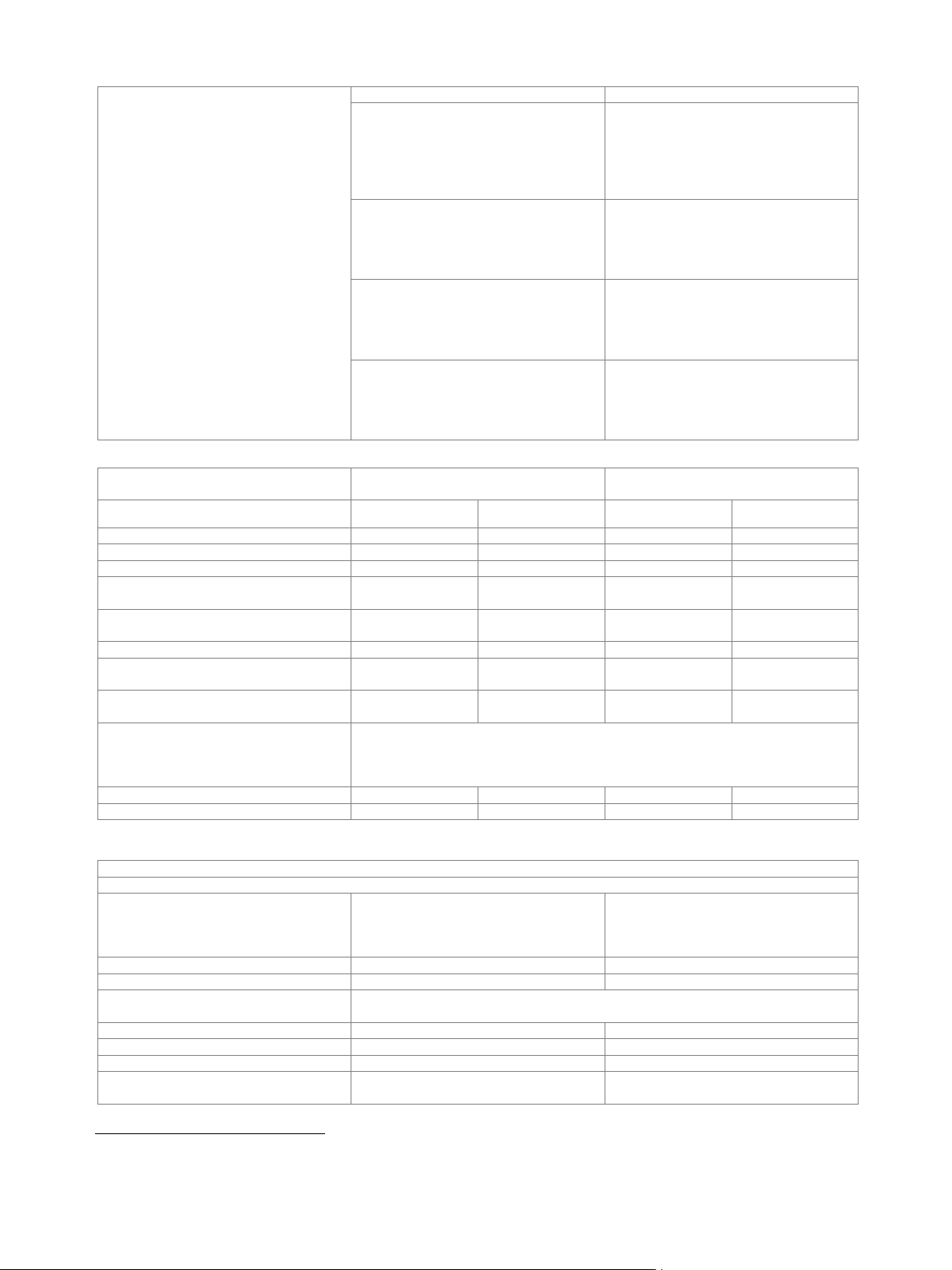
Bandwidth (RF)
general
according to selected system configuration
system configuration mode: standard
bandwidth of wideband baseband
generator (see section Wideband
baseband generator, specification for
R&S
®
SMW-B9 option) or maximum
specified bandwidth (RF) of the selected
interface, whichever is smaller
system configuration mode: advanced
200 MHz or maximum specified bandwidth
(RF) of the selected interface, whichever is
smaller (see section Multichannel, MIMO,
fading and noise, specifications for
R&S
®
SMW-K75/-K821 options)
with R&S
®
SMW-K822 option
400 MHz or maximum specified bandwidth
(RF) of the selected interface, whichever is
smaller (see section Multichannel, MIMO,
fading and noise, specifications for
R&S
®
SMW-K75/-K821 options)
with R&S
®
SMW-K823 option
800 MHz or maximum specified bandwidth
(RF) of the selected interface, whichever is
smaller (see section Multichannel, MIMO,
fading and noise, specifications for
R&S
®
SMW-K75/-K821 options)
Minimum required R&S
®
SMW200A
options
Digital I/Q inputs
Digital I/Q outputs
Interface standard
DIG I/Q
HS DIG I/Q
DIG I/Q
HS DIG I/Q
R&S
®
SMW-B13XT + 1 × R&S
®
SMW-K19
–
–
1
1
R&S
®
SMW-B13XT + 2 × R&S
®
SMW-K19
–
–
2
2
1 × R&S
®
SMW-B9 + R&S
®
SMW-B13XT
1
1
–
–
1 × R&S
®
SMW-B9 + R&S
®
SMW-B13XT +
1 × R&S
®
SMW-K19
1
1
1
1
1 × R&S
®
SMW-B9 + R&S
®
SMW-B13XT +
2 × R&S
®
SMW-K19
1
1
2
2
2 × R&S
®
SMW-B9 + R&S
®
SMW-B13XT
2
2
–
–
2 × R&S
®
SMW-B9 + R&S
®
SMW-B13XT +
1 × R&S
®
SMW-K19
2
2
1
1
2 × R&S
®
SMW-B9 + R&S
®
SMW-B13XT +
2 × R&S
®
SMW-K19
2
2
2
2
2 × R&S
®
SMW-B9 +
4 × R&S
®
SMW-B15 + R&S
®
SMW-B13XT +
2 × R&S
®
SMW-K19
depends on selected system configuration
(for required additional options for specific system configurations, see section
Multichannel, MIMO, fading and noise, specifications for R&S
®
SMW-K74, -K75, -K76
options)
2×1×1
2
2
2
2
other
–
–
up to 8
2
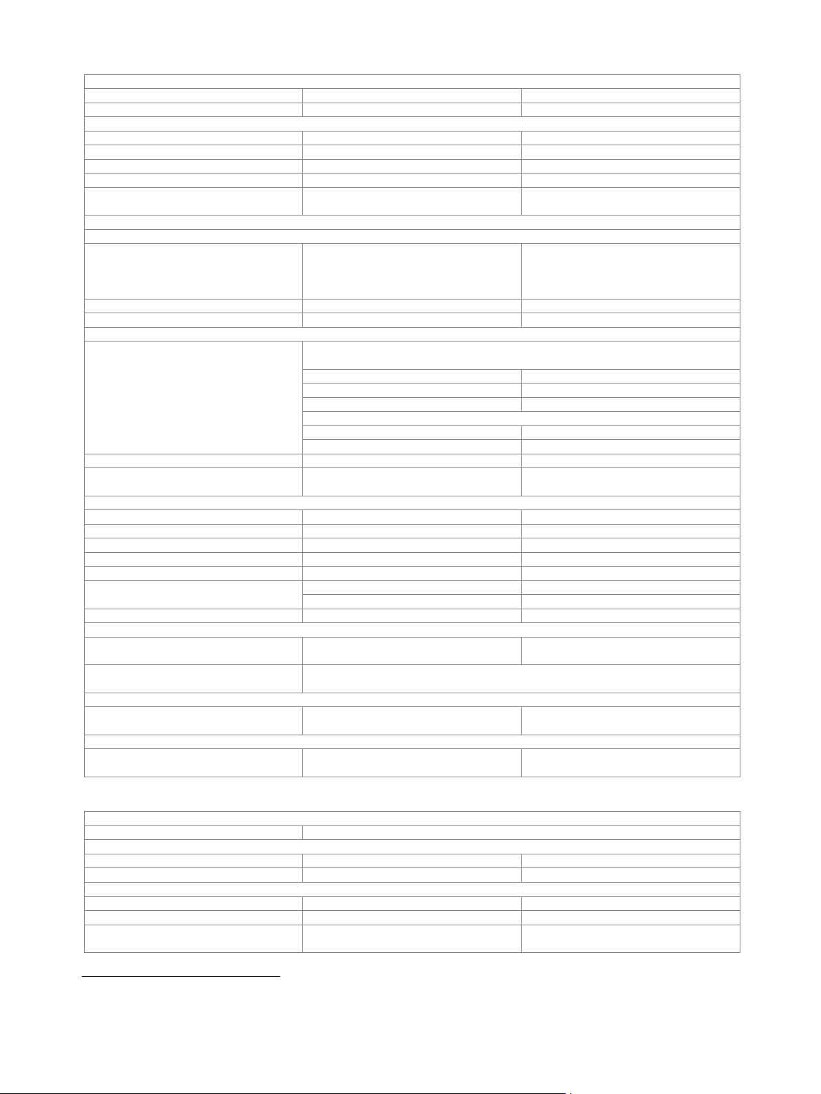
Output parameters
DIG I/Q interface
Interface
Standard
DIG I/Q, in line with
R&S
®
Digital I/Q Interface PAD-R
19
,
I/Q data and control signals, data and
interface clock
Level
LVDS
Connector
26-pin MDR
I/Q sample rate
With source "user-defined", the sample rate must be entered via the parameter
"sample rate".
Source
user-defined
Sample rate
250 MHz
Resolution
source: user-defined
0.001 Hz
Frequency uncertainty
source: user-defined
< (1 · 10
−12
+ relative deviation of
reference frequency) · sample rate (nom.)
19
R&S
®
Digital I/Q Interface PAD-R is a Rohde & Schwarz internal company guideline for the transmission of digital I/Q data. It is supported by a wide
range of signal generators, signal analyzers and radio communication testers.
Version 27.00, October 2024
Rohde & Schwarz R&S
®
SMW200A Vector Signal Generator 55
I/Q data
Resolution
18 bit
Logic format
two’s complement
Physical signal level
Setting range
0 to –60 dBFS
Resolution
0.01 dBFS
Bandwidth (RF)
system configuration mode: advanced
0.8 · sample rate
Control signals
markers
3
Earliest supported R&S
®
SMW200A
firmware version
4.30.046.221
HS DIQ I/Q interface
Interface
Standard
HS DIG I/Q,
in line with R&S
®
Digital I/Q Interface 40G
PAD-R
20
(DIG I/Q 40G),
I/Q data and control signals
Level
LVDS
Connector
QSFP+ / QSFP 28
I/Q sample rate
Sample rate
maximum sample rate depends on connected receiving device and system
configuration mode
system configuration mode: standard
40G
up to 1.05 GHz
50G
up to 1.25 GHz
system configuration mode: advanced
analog and digital (HS)
1000 MHz
digital only (HS)
up to 250 MHz
Resolution
0.001 Hz
Frequency uncertainty
< (1 · 10
−12
+ relative deviation of
reference frequency) · sample rate (nom.)
I/Q data
Resolution
up to 16 bit
Logic format
two’s complement
Physical signal level
Setting range
0 to –60 dBFS
Setting resolution
0.01 dBFS
Bandwidth (RF)
system configuration mode: standard
0.83 · sample rate
system configuration mode: advanced
0.8 · sample rate
Control signals
markers
2
Setup external RF with R&S
®
SMW-B13XT to R&S
®
SMW-B9
Earliest supported R&S
®
SMW200A
firmware version
4.70.128.xx
Notes
If both R&S
®
SMW200A have DACW board revision 4.00 and DACW board revision
5.00, use DACW board revision 5.00 as signal source.
Setup external RF with R&S
®
SMW-B13XT to R&S
®
SMM100A
Earliest supported R&S
®
SMW200A
firmware version
4.90.049.xx
Setup external RF with R&S
®
SMW-B13XT to R&S
®
SMCV100B
Earliest supported R&S
®
SMW200A
firmware version
4.90.049.xx
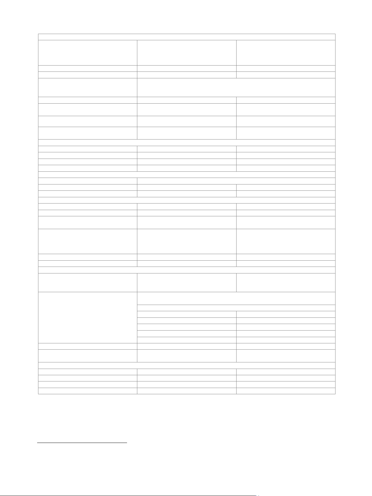
Input parameters
DIQ I/Q interface
Input level
peak level
Peak level
Setting range
referenced to full scale
–60 dB to +3 dB
Resolution
0.01 dB
Crest factor
Setting range
0 dB to +30 dB
Resolution
0.01 dB
Adjust level function
automatically determines peak level and
crest factor of input signal
20
R&S
®
Digital I/Q Interface 40G PAD-R is a Rohde & Schwarz internal company guideline for the transmission of digital I/Q data. It is supported by a
wide range of signal generators, signal analyzers and radio communication testers.
Version 27.00, October 2024
56 Rohde & Schwarz R&S
®
SMW200A Vector Signal Generator
Interface
Standard
DIG I/Q, in line with
R&S
®
Digital I/Q Interface PAD-R
21
,
I/Q data and control signals, data and
interface clock
Level
LVDS
Connector
26-pin MDR
I/Q sample rate
With source "user-defined", the sample rate must be entered via the parameter
"sample rate". With source "Digital I/Q In", the sample rate will be used based on
information provided by the transmitting device.
Source
user-defined, Digital I/Q In
Sample rate
maximum sample rate depends on
connected receiving device
400 Hz to 250 MHz
Resolution
source: user-defined
0.001 Hz
Frequency uncertainty
source: user-defined
< (1 · 10
−12
+ relative deviation of
reference frequency) · sample rate (nom.)
I/Q data
Resolution
18 bit
Logic format
two’s complement
Bandwidth (RF)
system configuration mode: advanced
0.8 · sample rate
Control signals
markers
3
HS DIQ I/Q interface
Input level
peak level
Setting range
–60 dB to +3 dB, referenced to full scale
Setting resolution
0.01 dB
Crest factor
Setting range
0 dB to +30 dB
Setting resolution
0.01 dB
Adjust level function
automatically determines peak level and
crest factor of input signal
Standard
HS DIG I/Q, in line with
R&S
®
Digital I/Q Interface 40G PAD-R
21
(DIG I/Q 40G), I/Q data and control
signals
Level
LVDS
Connector
QSFP+ / QSFP 28
I/Q sample rate
Source
the sample rate will be used based on
information provided by the transmitting
device
HS digital I/Q In
Sample rate
maximum sample rate depends on connected transmitting device and system
configuration mode
system configuration mode: standard
40G
up to 1.05 GHz
50G
up to 1.25 GHz
system configuration mode: advanced
up to 250 MHz
with R&S
®
SMW-K822 option
up to 500 MHz
with R&S
®
SMW-K823 option
up to 1000 MHz
Resolution
0.001 Hz
Frequency uncertainty
< (1 · 10
−12
+ relative deviation of
reference frequency) · sample rate (nom.)
I/Q data
Resolution
16 bit
Logic format
two’s complement
Bandwidth (RF)
system configuration mode: standard
0.83 · sample rate
Control signals
markers
2
21
R&S
®
Digital I/Q Interface PAD-R is a Rohde & Schwarz internal company guideline for the transmission of digital I/Q data. It is supported by a wide
range of signal generators, signal analyzers and radio communication testers.