SMW200A_specs_en_3606-8037-22_v2700.pdf - 第63页
Version 27.00, October 2024 Rohde & Schwar z R&S ® SMW200A Vec tor Signal Generator 63 Mandatory extra 40G QSFP+ to 10G SFP+ adapter converter module Recommended extras • 10G SFP+ opti cal cable • 10G SFP+ Ethern…

Version 27.00, October 2024
62 Rohde & Schwarz R&S
®
SMW200A Vector Signal Generator
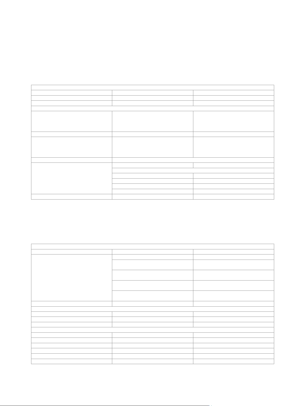
Agile sequencing (R&S
®
SMW-K506 option)
Agile sequencing allows external control and fast arbitrary switching of prestored ARB segments by streaming of ARB descriptor
words (ADW) including a waveform ID to the R&S
®
SMW200A. The R&S
®
SMW-K506 option enhances the R&S
®
SMW-B9 wideband
baseband generator option by adding ADW streaming via a dedicated, low latency 10 Gbit/s LAN interface over an existing QSFP+
interface.
In addition to ARB segment sequencing, the interface provides agile switching of frequency, phase and amplitude. These variations
are applied in real time.
At least one R&S
®
SMW-B9 wideband baseband generator option must be installed. If two R&S
®
SMW-B9 options are installed (signal
paths A and B), the agile sequencing can be used either on signal path A or B with one R&S
®
SMW-K506 option. For simultaneous
usage on signal paths A and B, two R&S
®
SMW-K506 options must be installed.
ADW parameters
ADW format
Size
32 byte fixed length
Controllable parameters
frequency offset, amplitude offset, phase
offset, waveform ID, segment repetitions,
segment interrupt
Setting granularity
Amplitude offset
16 bit (voltage based)
Phase offset
< 0.01°
Frequency offset
0.58 Hz
ARB segments
Maximum individual segments
16 777 216
Length granularity
32 samples
Time parameters
Minimum ARB segment playback
repetition interval
1.0 µs
Operating modes
Deterministic
ADW execution on external trigger event
Trigger to RF delay
depends on ARB sample rate
sample rate = 37.5 MHz
5.6 µs (meas.)
sample rate = 75 MHz
4.1 µs (meas.)
sample rate = 300 MHz
3.4 µs (meas.)
sample rate = 2.4 GHz
3.1 µs (meas.)
Trigger jitter
±1.67 ns
ARB segment repetitions
looping of ARB segments
1 to 2
16
Instant
instant ADW execution after reception
ADW reception to RF delay
depends on ARB sample rate
sample rate = 37.5 MHz
7.3 µs (meas.)
sample rate = 75 MHz
5.5 µs (meas.)
sample rate = 300 MHz
4.7 µs (meas.)
sample rate = 2.4 GHz
4.3 µs (meas.)
ARB segment repetitions
looping of ARB segments
1 to 2
16
Marker signals
Number of marker signals
3
Operating modes
pulse, restart, ADW
Marker outputs
see section Wideband baseband
generator (R&S
®
SMW-B9 option) –
arbitrary waveform mode
Marker delay
see section Wideband baseband
generator (R&S
®
SMW-B9 option) –
arbitrary waveform mode
Interface parameters
LAN interface
Connector
HS/DIGIQ 1, 2 on rear panel
QSFP+ (note the extras below)
Protocol
UDP over Ethernet
Data rate
10 Gbit/s
Trigger input connector
see section Wideband baseband
generator (R&S
®
SMW-B9 option) –
arbitrary waveform mode
Ready for trigger output connector
see section Wideband baseband
generator (R&S
®
SMW-B9 option) –
arbitrary waveform mode
Internal ADW buffer
Size
512 ADWs

Version 27.00, October 2024
Rohde & Schwarz R&S
®
SMW200A Vector Signal Generator 63
Mandatory extra
40G QSFP+ to 10G SFP+ adapter
converter module
Recommended extras
• 10G SFP+ optical cable
• 10G SFP+ Ethernet network interface
card
Wideband baseband generator (R&S
®
SMW-B9 option) – real-time operation
(custom digital modulation)
See Digital Standards for Signal Generators specifications (PD 5213.9434.22).
Wideband baseband generator for GNSS with high dynamics
(R&S
®
SMW-B9F option)
This wideband baseband generator enables high dynamics with GNSS standards. For details see the GNSS simulation for
Rohde & Schwarz vector signal generators specifications (PD 3607.6896.22). Otherwise, the specifications of the wideband baseband
generator (R&S
®
SMW-B9 option) also apply for the R&S
®
SMW-B9F option. Enhancements of the R&S
®
SMW-B9 option and software
options that run on the R&S
®
SMW-B9 option also work with the R&S
®
SMW-B9F option.
Note that R&S
®
SMW-B9F and R&S
®
SMW-B9 cannot be mixed, i.e. only the following configurations can be installed:
• 1 × R&S
®
SMW-B9
• 2 × R&S
®
SMW-B9
• 1 × R&S
®
SMW-B9F
• 2 × R&S
®
SMW-B9F
Version 27.00, October 2024
64 Rohde & Schwarz R&S
®
SMW200A Vector Signal Generator
Baseband enhancements
Additive white Gaussian noise (AWGN) (R&S
®
SMW-K62 option)
AWGN can be generated either on path A or B with one R&S
®
SMW-K62 option. For AWGN to be generated on paths A and B
simultaneously, two R&S
®
SMW-K62 must be installed, and the R&S
®
SMW200A must be equipped with the R&S
®
SMW-B13T or
R&S
®
SMW-B13XT option.
Addition of an AWGN signal of settable bandwidth and settable C/N ratio or E
b
/N
0
to a wanted signal. If the noise generator is used,
a frequency offset cannot be added to the wanted signal.
Noise
Distribution density
Gaussian, statistical, separate for I and Q
Crest factor
> 15 dB
Periodicity
> 3 · 10
10
s
C/N, E
b
/N
0
Setting range
Depends on the set RF level.
The PEP of the sum signal (wanted signal
+ noise) must not exceed the maximum
possible PEP of the respective RF path.
–50 dB to +45 dB
Setting resolution
0.01 dB
Uncertainty
for system bandwidth = symbol rate,
symbol rate < 4 MHz,
–24 dB < C/N < 30 dB and
crest factor < 12 dB
< 0.1 dB
System bandwidth
bandwidth for determining noise power
Setting range
with R&S
®
SMW-B13/-B13T options
1 kHz to 160 MHz
with R&S
®
SMW-B13XT option
system configuration mode: standard
1 kHz to 2000 MHz
system configuration mode: advanced
1 kHz to 200 MHz
with R&S
®
SMW-K822 option
1 kHz to 400 MHz
with R&S
®
SMW-K823 option
1 kHz to 800 MHz
Setting resolution
100 Hz
Enhanced noise generation (R&S
®
SMW-K810 option)
Enhanced noise generation can be used either on signal path A or B with one R&S
®
SMW-K810 option. For enhanced noise
generation to be used on paths A and B simultaneously, two R&S
®
SMW-K810 must be installed. For each R&S
®
SMW-K810 option to
be installed, an R&S
®
SMW-K62 option must be installed as prerequisite.
Phase noise simulation
Phase noise
Injection
after fading
Profiles
user-defined
user
predefined PLL phase noise profiles
(simulation of typical PLL circuits)
PLL 1, PLL 2
predefined VCXO phase noise profiles
(simulation of typical oscillator circuits)
crystal 1 to 5
predefined DVB-S2 phase noise profiles,
based on EN 302307, DIRECTV
DVB-S2 P1, DVB-S2 P2, DVB-S2 D1,
DVB-S2 A1, DVB-S2 A2
predefined ATSC phase noise profiles,
based on ATSC A.74
ATSC A.74
File format
text files, editable
Graphical user interface
Entry
by curve table
Number of nodes
5 independent points
Calculation
internal
Amplitude at f
carrier
± 100 Hz
Setting range
measurement bandwidth = 1 Hz
–110.00 dBc to 0.00 dBc
Setting resolution
measurement bandwidth = 1 Hz
0.01 dB
Maximum phase angle
±180°
Density distribution function
Gaussian
Frequency response
depends on phase noise profile
System bandwidth
10 MHz