SMW200A_specs_en_3606-8037-22_v2700.pdf - 第54页
Version 27.00, October 2024 54 Rohde & Schwar z R&S ® SMW200A Vec tor Signal Generator Bandwidth (RF) general according to sele cted system con figuration system configura tion mode: stand ard bandwidth of wideba…
Version 27.00, October 2024
Rohde & Schwarz R&S
®
SMW200A Vector Signal Generator 53
Digital baseband inputs/outputs for wideband baseband
Depending on the installed software and hardware options, the R&S
®
SMW200A is able to receive digital baseband signals and output
digital baseband signals. The digital I/Q input/output can be used for the lossless connection of the R&S
®
SMW200A to the digital I/Q
input/output of other Rohde & Schwarz instruments.
Digital baseband outputs: At least one R&S
®
SMW-K19 option must be installed. Digital baseband outputs can be used either on signal
path A or B with one R&S
®
SMW-K19 option. For digital baseband outputs to be used on signal paths A and B simultaneously,
two R&S
®
SMW-K19 must be installed. To enable two or more digital baseband outputs in multichannel or other advanced modes,
two R&S
®
SMW-K19 must be installed.
The R&S
®
SMW-K19 option requires R&S
®
SMW-B13XT with DACW board revision 4.00 or higher.
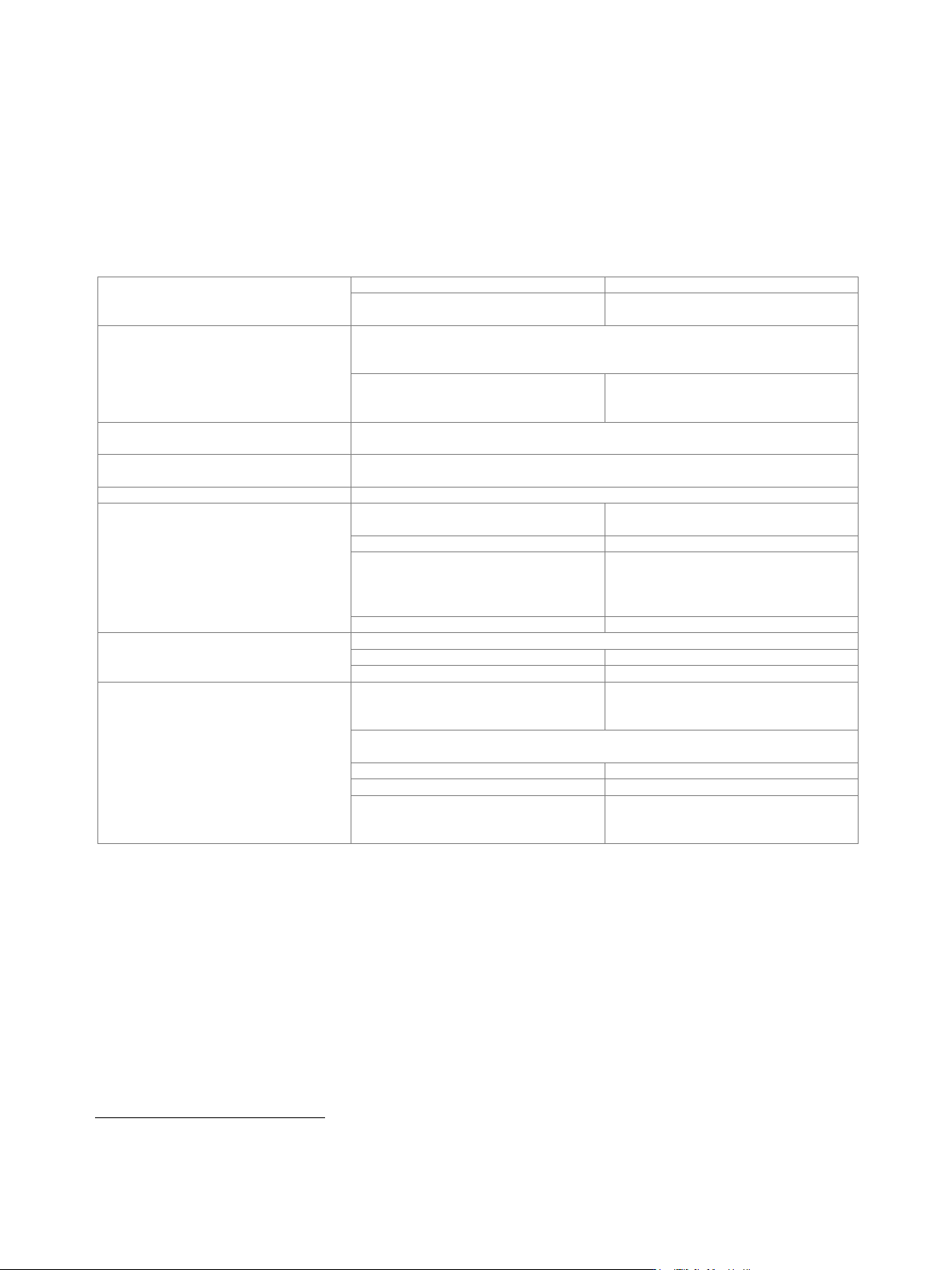
Signal outputs
system configuration mode: standard
analog only, digital only (HS
17
)
system configuration mode: advanced
18
analog and digital, analog and digital (HS),
digital only (HS)
Digital only (HS)
The streams are output via the digital I/Q outputs only (HS DIG I/Q interface standard).
Analog I/Q outputs are not available. External modulation signals can be output via the
RF outputs (I/Q modulation mode: external wideband I/Q).
with R&S
®
SMW-K551 installed and
system configuration mode: advanced
The instrument runs at reduced speed,
depending on the device connected to the
digital I/Q output (slow I/Q).
Analog and digital
The instrument runs in regular operating mode, both analog and digital outputs
(DIG I/Q interface standard) are available.
Analog and digital (HS)
The instrument runs in regular operating mode, both analog and digital outputs
(HS DIG I/Q interface standard) are available.
Analog only
The instrument runs in regular operating mode, only analog outputs are available.
Number of digital outputs
according to selected system configuration
(see table below)
signal outputs: digital only (HS)
maximum 2 (on R&S
®
SMW-B13XT)
signal outputs: analog and digital
maximum 8 (on R&S
®
SMW-B13XT and
R&S
®
SMW-B15) depending on
entities · RX antennas of MIMO/SIMO
configuration
signal outputs: analog and digital (HS)
maximum 2 (on R&S
®
SMW-B13XT)
Number of streams per output
signal outputs: digital only (HS)
system configuration mode: standard
1 to 2
system configuration mode: advanced
1 to 8
Number of streams per input
system configuration mode: standard;
signal outputs: analog only,
HS DIG I/Q
1 to 2
system configuration mode: advanced; signal outputs: analog and digital,
200 MHz, interface either DIG I/Q or HS DIG I/Q
HS DIG I/Q
1 to 2
DIG I/Q
1 to 2
system configuration mode: advanced;
signal outputs: analog and digital,
400 MHz or 800 MHz, HS DIQ I/Q
1 to 2
17
HS = high-speed.
18
The following functions are not available in advanced system configuration mode: analog modulation, modulation sources for analog modulation,
envelope tracking, AM/AM, AM/PM predistortion, Digital Doherty.
Version 27.00, October 2024
54 Rohde & Schwarz R&S
®
SMW200A Vector Signal Generator
Bandwidth (RF)
general
according to selected system configuration
system configuration mode: standard
bandwidth of wideband baseband
generator (see section Wideband
baseband generator, specification for
R&S
®
SMW-B9 option) or maximum
specified bandwidth (RF) of the selected
interface, whichever is smaller
system configuration mode: advanced
200 MHz or maximum specified bandwidth
(RF) of the selected interface, whichever is
smaller (see section Multichannel, MIMO,
fading and noise, specifications for
R&S
®
SMW-K75/-K821 options)
with R&S
®
SMW-K822 option
400 MHz or maximum specified bandwidth
(RF) of the selected interface, whichever is
smaller (see section Multichannel, MIMO,
fading and noise, specifications for
R&S
®
SMW-K75/-K821 options)
with R&S
®
SMW-K823 option
800 MHz or maximum specified bandwidth
(RF) of the selected interface, whichever is
smaller (see section Multichannel, MIMO,
fading and noise, specifications for
R&S
®
SMW-K75/-K821 options)
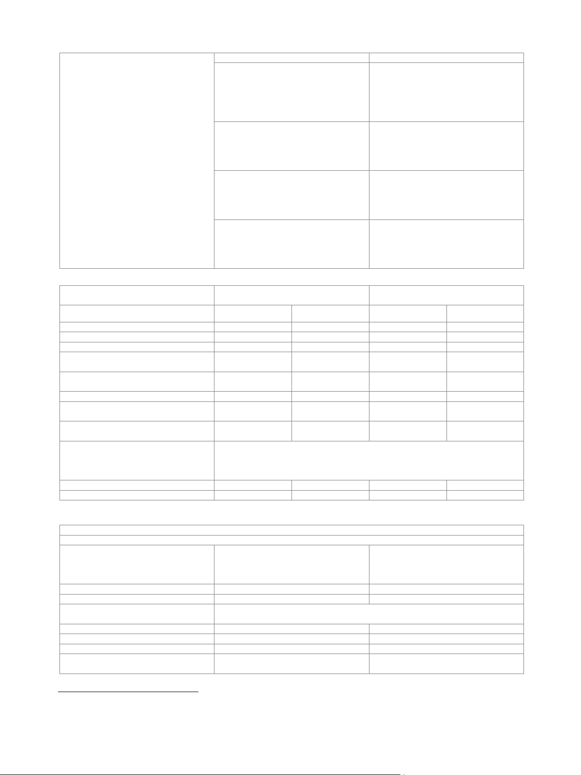
Minimum required R&S
®
SMW200A
options
Digital I/Q inputs
Digital I/Q outputs
Interface standard
DIG I/Q
HS DIG I/Q
DIG I/Q
HS DIG I/Q
R&S
®
SMW-B13XT + 1 × R&S
®
SMW-K19
–
–
1
1
R&S
®
SMW-B13XT + 2 × R&S
®
SMW-K19
–
–
2
2
1 × R&S
®
SMW-B9 + R&S
®
SMW-B13XT
1
1
–
–
1 × R&S
®
SMW-B9 + R&S
®
SMW-B13XT +
1 × R&S
®
SMW-K19
1
1
1
1
1 × R&S
®
SMW-B9 + R&S
®
SMW-B13XT +
2 × R&S
®
SMW-K19
1
1
2
2
2 × R&S
®
SMW-B9 + R&S
®
SMW-B13XT
2
2
–
–
2 × R&S
®
SMW-B9 + R&S
®
SMW-B13XT +
1 × R&S
®
SMW-K19
2
2
1
1
2 × R&S
®
SMW-B9 + R&S
®
SMW-B13XT +
2 × R&S
®
SMW-K19
2
2
2
2
2 × R&S
®
SMW-B9 +
4 × R&S
®
SMW-B15 + R&S
®
SMW-B13XT +
2 × R&S
®
SMW-K19
depends on selected system configuration
(for required additional options for specific system configurations, see section
Multichannel, MIMO, fading and noise, specifications for R&S
®
SMW-K74, -K75, -K76
options)
2×1×1
2
2
2
2
other
–
–
up to 8
2
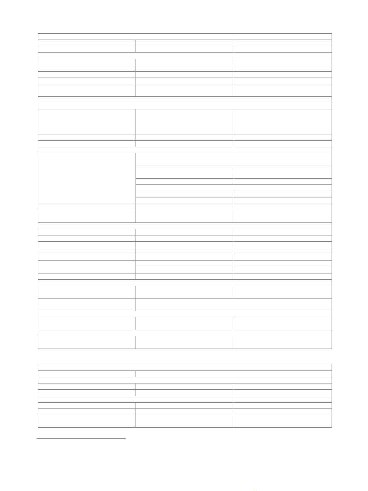
Output parameters
DIG I/Q interface
Interface
Standard
DIG I/Q, in line with
R&S
®
Digital I/Q Interface PAD-R
19
,
I/Q data and control signals, data and
interface clock
Level
LVDS
Connector
26-pin MDR
I/Q sample rate
With source "user-defined", the sample rate must be entered via the parameter
"sample rate".
Source
user-defined
Sample rate
250 MHz
Resolution
source: user-defined
0.001 Hz
Frequency uncertainty
source: user-defined
< (1 · 10
−12
+ relative deviation of
reference frequency) · sample rate (nom.)
19
R&S
®
Digital I/Q Interface PAD-R is a Rohde & Schwarz internal company guideline for the transmission of digital I/Q data. It is supported by a wide
range of signal generators, signal analyzers and radio communication testers.
Version 27.00, October 2024
Rohde & Schwarz R&S
®
SMW200A Vector Signal Generator 55
I/Q data
Resolution
18 bit
Logic format
two’s complement
Physical signal level
Setting range
0 to –60 dBFS
Resolution
0.01 dBFS
Bandwidth (RF)
system configuration mode: advanced
0.8 · sample rate
Control signals
markers
3
Earliest supported R&S
®
SMW200A
firmware version
4.30.046.221
HS DIQ I/Q interface
Interface
Standard
HS DIG I/Q,
in line with R&S
®
Digital I/Q Interface 40G
PAD-R
20
(DIG I/Q 40G),
I/Q data and control signals
Level
LVDS
Connector
QSFP+ / QSFP 28
I/Q sample rate
Sample rate
maximum sample rate depends on connected receiving device and system
configuration mode
system configuration mode: standard
40G
up to 1.05 GHz
50G
up to 1.25 GHz
system configuration mode: advanced
analog and digital (HS)
1000 MHz
digital only (HS)
up to 250 MHz
Resolution
0.001 Hz
Frequency uncertainty
< (1 · 10
−12
+ relative deviation of
reference frequency) · sample rate (nom.)
I/Q data
Resolution
up to 16 bit
Logic format
two’s complement
Physical signal level
Setting range
0 to –60 dBFS
Setting resolution
0.01 dBFS
Bandwidth (RF)
system configuration mode: standard
0.83 · sample rate
system configuration mode: advanced
0.8 · sample rate
Control signals
markers
2
Setup external RF with R&S
®
SMW-B13XT to R&S
®
SMW-B9
Earliest supported R&S
®
SMW200A
firmware version
4.70.128.xx
Notes
If both R&S
®
SMW200A have DACW board revision 4.00 and DACW board revision
5.00, use DACW board revision 5.00 as signal source.
Setup external RF with R&S
®
SMW-B13XT to R&S
®
SMM100A
Earliest supported R&S
®
SMW200A
firmware version
4.90.049.xx
Setup external RF with R&S
®
SMW-B13XT to R&S
®
SMCV100B
Earliest supported R&S
®
SMW200A
firmware version
4.90.049.xx
Input parameters
DIQ I/Q interface
Input level
peak level
Peak level
Setting range
referenced to full scale
–60 dB to +3 dB
Resolution
0.01 dB
Crest factor
Setting range
0 dB to +30 dB
Resolution
0.01 dB
Adjust level function
automatically determines peak level and
crest factor of input signal
20
R&S
®
Digital I/Q Interface 40G PAD-R is a Rohde & Schwarz internal company guideline for the transmission of digital I/Q data. It is supported by a
wide range of signal generators, signal analyzers and radio communication testers.