SMW200A_specs_en_3606-8037-22_v2700.pdf - 第39页
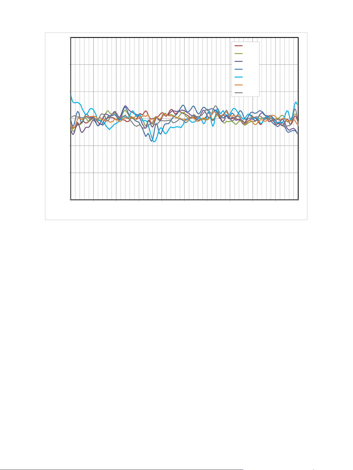
Version 27.00, October 2024 Rohde & Schwar z R&S ® SMW200A Vec tor Signal Generator 39 Measured RF modu lation frequen cy response (phase) with internal baseban d I/Q, wideband baseb and -30.0 -20.0 -10.0 0.0 10.…
Version 27.00, October 2024
38 Rohde & Schwarz R&S
®
SMW200A Vector Signal Generator
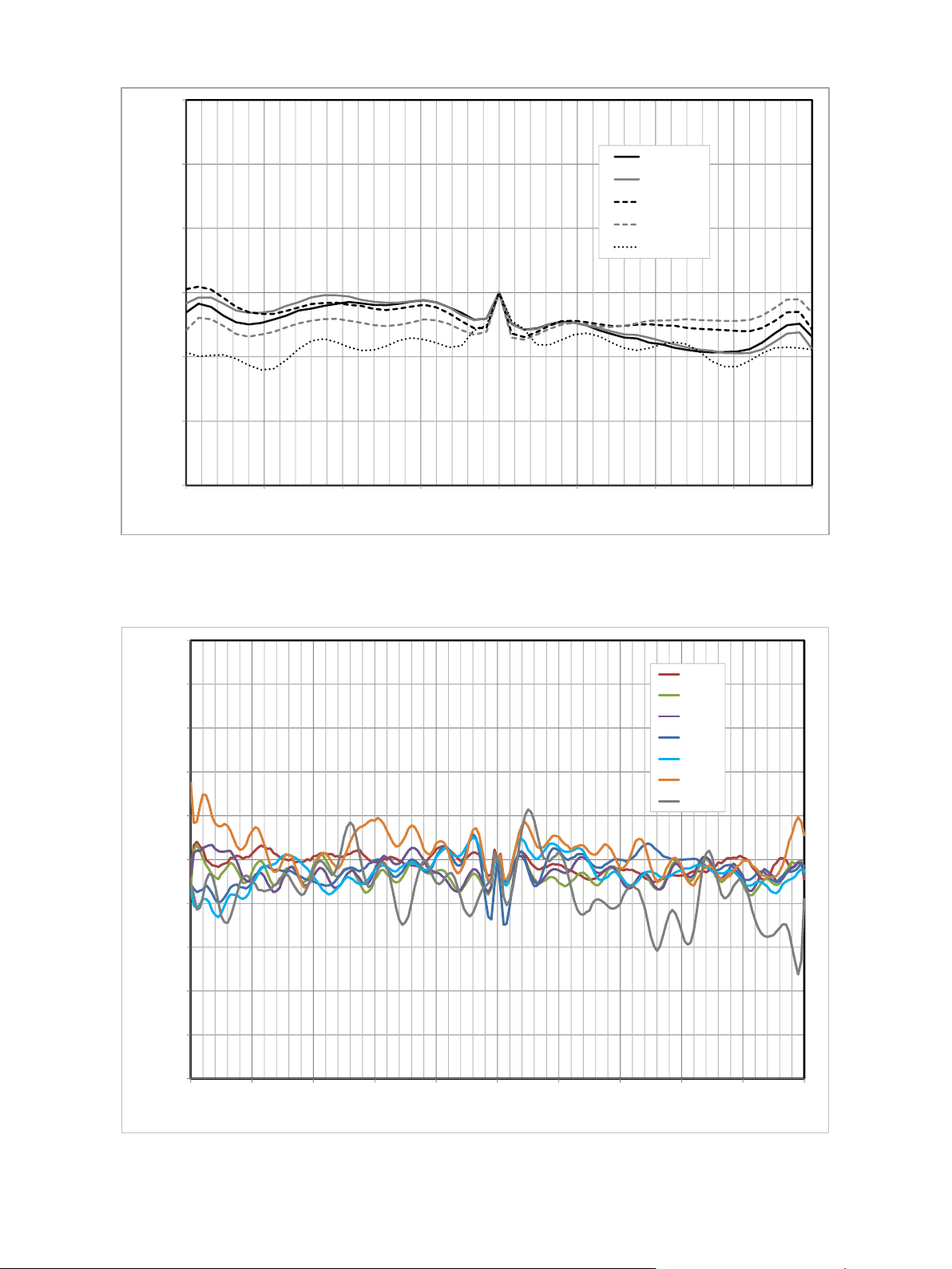
Measured RF modulation frequency response (magnitude) with internal baseband I/Q, standard baseband
Measured RF modulation frequency response (magnitude) with internal baseband I/Q, wideband baseband
-0.30
-0.20
-0.10
0.00
0.10
0.20
0.30
-80 -60 -40 -20 0 20 40 60 80
Frequency response / dB
Offset frequency / MHz
850 MHz
2140 MHz
5400 MHz
10000 MHz
25000 MHz
-0.50
-0.40
-0.30
-0.20
-0.10
0.00
0.10
0.20
0.30
0.40
0.50
-1000 -800 -600 -400 -200 0 200 400 600 800 1000
Frequency response (magnitude) / dB
Offset frequency / MHz
5 GHz
15 GHz
18 GHz
28 GHz
35 GHz
48 GHz
64 GHz
Version 27.00, October 2024
Rohde & Schwarz R&S
®
SMW200A Vector Signal Generator 39
Measured RF modulation frequency response (phase) with internal baseband I/Q, wideband baseband
-30.0
-20.0
-10.0
0.0
10.0
20.0
30.0
-1000 -800 -600 -400 -200 0 200 400 600 800 1000
Frequency response (phase) /
°
Offset frequency / MHz
5 GHz
15 GHz
18 GHz
28 GHz
35 GHz
48 GHz
64 GHz
Version 27.00, October 2024
40 Rohde & Schwarz R&S
®
SMW200A Vector Signal Generator
Analog I/Q inputs
For each installed RF path A or B, one pair of I and Q inputs is available on the front panel (single-ended input mode). With the
R&S
®
SMW-K739 option installed, the input mode for RF path A can also be switched to differential. In this mode, all four available
connectors are used for RF path A.
Analog I/Q input signals are directly applied to the analog I/Q modulation circuit and are not routed through the baseband section of
the R&S
®
SMW200A.
Analog I/Q inputs are not available if an R&S
®
SMW-B1044O, R&S
®
SMW-B2044O, R&S
®
SMW-B1056O or R&S
®
SMW-B1067O option
is installed.
Input mode
single-ended
with R&S
®
SMW-K739 option, for RF path A
R&S
®
SMW-B1003, R&S
®
SMW-B1006,
R&S
®
SMW-B1007, R&S
®
SMW-B1012,
R&S
®
SMW-B1020, R&S
®
SMW-B1044,
R&S
®
SMW-B1044N
single-ended or differential
R&S
®
SMW-B1031, R&S
®
SMW-B1040, R&S
®
SMW-B1040N
f ≤ 20 GHz
single-ended or differential
f > 20 GHz
single-ended
Connector types
I, Q on front panel (for each installed
RF path A or B)
BNC female
Input impedance
50 Ω (nom.)
VSWR
with R&S
®
SMW-B1003, R&S
®
SMW-B2003, R&S
®
SMW-B1006, R&S
®
SMW-B2006,
R&S
®
SMW-B1007, R&S
®
SMW-B2007, R&S
®
SMW-B1012, R&S
®
SMW-B2012,
R&S
®
SMW-B1020, R&S
®
SMW-B2020 frequency options
up to 200 MHz
< 1.2 (typ.)
200 MHz to 500 MHz
< 1.35 (typ.)
500 MHz to 1 GHz
< 1.45 (typ.)
with R&S
®
SMW-B1031, R&S
®
SMW-B2031, R&S
®
SMW-B1040, R&S
®
SMW-B1044,
R&S
®
SMW-B2044, R&S
®
SMW-B1056, R&S
®
SMW-B1067 frequency options
up to 200 MHz, f ≤ 20 GHz
< 1.2 (typ.)
up to 200 MHz, f > 20 GHz
< 1.35 (typ.)
200 MHz to 500 MHz
< 1.35 (typ.)
500 MHz to 1 GHz
< 1.5 (typ.)
with R&S
®
SMW-B1040N, R&S
®
SMW-B1044N, R&S
®
SMW-B2044N,
R&S
®
SMW-B1056N, R&S
®
SMW-B1067N frequency options
up to 200 MHz, f ≤ 20 GHz
< 1.2 (typ.)
200 MHz to 500 MHz, f ≤ 20 GHz
< 1.35 (typ.)
500 MHz to 1 GHz, f ≤ 20 GHz
< 1.5 (typ.)
up to 275 MHz, f > 20 GHz
< 1.35 (typ.)
Nominal input voltage for full-scale input
Damage voltage
±2 V
q
22
i
+ = 0.5 V
VV