SMW200A_specs_en_3606-8037-22_v2700.pdf - 第8页
Version 27.00, October 2024 8 Rohde & Schwar z R&S ® SMW200A Vec tor Signal Generator Baseband hardware o verview To select between two different baseband sect ions, simply choose the appropriate baseban d main m…
Version 27.00, October 2024
Rohde & Schwarz R&S
®
SMW200A Vector Signal Generator 7
Frequency and baseband main module options
Frequency options
One of the following frequency options must be installed in RF path A:
R&S
®
SMW-B1003
100 kHz to 3 GHz
R&S
®
SMW-B1006
100 kHz to 6 GHz
R&S
®
SMW-B1007
100 kHz to 7.5 GHz
R&S
®
SMW-B1012
100 kHz to 12.75 GHz
R&S
®
SMW-B1020
100 kHz to 20 GHz
R&S
®
SMW-B1031
100 kHz to 31.8 GHz
R&S
®
SMW-B1040, R&S
®
SMW-B1040N
100 kHz to 40 GHz
R&S
®
SMW-B1044, R&S
®
SMW-B1044N,
R&S
®
SMW-B1044O
100 kHz to 44 GHz
R&S
®
SMW-B1056, R&S
®
SMW-B1056N,
R&S
®
SMW-B1056O
100 kHz to 56 GHz
R&S
®
SMW-B1067, R&S
®
SMW-B1067N,
R&S
®
SMW-B1067O
100 kHz to 67 GHz
In addition, one of the following frequency options can be installed in RF path B:
R&S
®
SMW-B2003
100 kHz to 3 GHz
R&S
®
SMW-B2006
100 kHz to 6 GHz
R&S
®
SMW-B2007
100 kHz to 7.5 GHz
R&S
®
SMW-B2012
100 kHz to 12.75 GHz
R&S
®
SMW-B2020
100 kHz to 20 GHz
R&S
®
SMW-B2031
100 kHz to 31.8 GHz
R&S
®
SMW-B2044, R&S
®
SMW-B2044N,
R&S
®
SMW-B2044O
100 kHz to 44 GHz
The R&S
®
SMW-B1003, R&S
®
SMW-B2003, R&S
®
SMW-B1006, R&S
®
SMW-B2006, R&S
®
SMW-B1007, R&S
®
SMW-B2007,
R&S
®
SMW-B1012 and R&S
®
SMW-B2012 options include an electronic attenuator, whereas the R&S
®
SMW-B1020,
R&S
®
SMW-B2020, R&S
®
SMW-B1031, R&S
®
SMW-B2031, R&S
®
SMW-B1040, R&S
®
SMW-B1040N, R&S
®
SMW-B1044,
R&S
®
SMW-B2044, R&S
®
SMW-B1044N, R&S
®
SMW-B1044O, R&S
®
SMW-B2044N, R&S
®
SMW-B2044O, R&S
®
SMW-B1056,
R&S
®
SMW-B1056N, R&S
®
SMW-B1056O, R&S
®
SMW-B1067, R&S
®
SMW-B1067N and R&S
®
SMW-B1067O options include a
mechanical step attenuator.
For possible RF path combinations, see section Frequency options and RF path combinations.
Signal routing and baseband main module options
One of the following options must be installed:
R&S
®
SMW-B13
one I/Q path to RF section
R&S
®
SMW-B13T
two I/Q paths to RF section
R&S
®
SMW-B13XT
wideband, two I/Q paths to RF section
If RF path B is equipped with an R&S
®
SMW-B20xx frequency option, an R&S
®
SMW-B13T or R&S
®
SMW-B13XT option must be
installed as the baseband main module.
R&S
®
SMW-B13 and R&S
®
SMW-B13T cannot be installed in instruments equipped with R&S
®
SMW-B1044O, R&S
®
SMW-B2044O,
R&S
®
SMW-B1056O or R&S
®
SMW-B1067O frequency options.

Version 27.00, October 2024
8 Rohde & Schwarz R&S
®
SMW200A Vector Signal Generator
Baseband hardware overview
To select between two different baseband sections, simply choose the appropriate baseband main module.
To select the standard baseband section, choose the R&S
®
SMW-B13 or R&S
®
SMW-B13T option as the baseband main module. The
standard baseband section enables RF modulation bandwidths up to 160 MHz and allows further options for fading and MIMO to be
installed. It provides the following additional hardware options:
R&S
®
SMW-B10
standard baseband generator
R&S
®
SMW-B14
fading simulator
To select the wideband baseband section, choose the R&S
®
SMW-B13XT option as the baseband main module. The wideband
baseband section enables RF modulation bandwidths up to 2 GHz and allows further options for fading and MIMO to be installed.
It provides the following additional hardware options:
R&S
®
SMW-B9
wideband baseband generator
R&S
®
SMW-B9F
wideband baseband generator for GNSS with high dynamics
R&S
®
SMW-B15
fading simulator and signal processor
Version 27.00, October 2024
Rohde & Schwarz R&S
®
SMW200A Vector Signal Generator 9
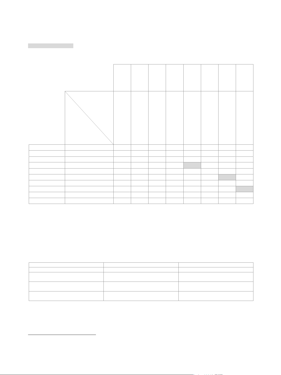
Frequency options and RF path combinations
The following RF path combinations are possible (● = possible, – = not possible).
Cells with grey background: These RF path combinations require the R&S
®
SMW-B94L option (deeper chassis).
Note that R&S
®
SMW-B94L is only possible with these RF path combinations.
Cells with white background: These RF path combinations come with the standard chassis (included in the base unit).
3 GHz
6 GHz
7.5 GHz
12.75 GHz
20 GHz
31.8 GHz
44 GHz
Path B
Path A
(path B not equipped)
R&S
®
SMW-B2003
R&S
®
SMW-B2006
R&S
®
SMW-B2007
R&S
®
SMW-B2012
R&S
®
SMW-B2020
R&S
®
SMW-B2031
R&S
®
SMW-B2044(N/O)
3 GHz
R&S
®
SMW-B1003
●
●
–
–
–
–
–
–
6 GHz
R&S
®
SMW-B1006
●
–
●
–
–
●
–
–
7.5 GHz
R&S
®
SMW-B1007
●
–
–
●
–
–
–
–
12.75 GHz
R&S
®
SMW-B1012
●
–
●
–
●
–
–
–
20 GHz
R&S
®
SMW-B1020
●
–
●
–
–
●
–
–
31.8 GHz
R&S
®
SMW-B1031
●
–
–
–
–
–
●
–
40 GHz
R&S
®
SMW-B1040(N)
●
–
–
–
–
–
–
–
44 GHz
R&S
®
SMW-B1044(N/O)
●
–
–
–
–
–
–
●
1
56 GHz
R&S
®
SMW-B1056(N/O)
●
–
–
–
–
–
–
–
67 GHz
R&S
®
SMW-B1067(N/O)
●
–
–
–
–
–
–
–
Low phase noise options
The R&S
®
SMW200A can be equipped with different types of low phase noise options, providing different levels of phase noise
performance.
As a general rule, all installed RF paths must have the same phase noise performance level. For example, if RF path A is equipped
with an ultra low phase noise option, and a second RF path (B) shall be installed, the second RF path must also be equipped with an
ultra low phase noise option.
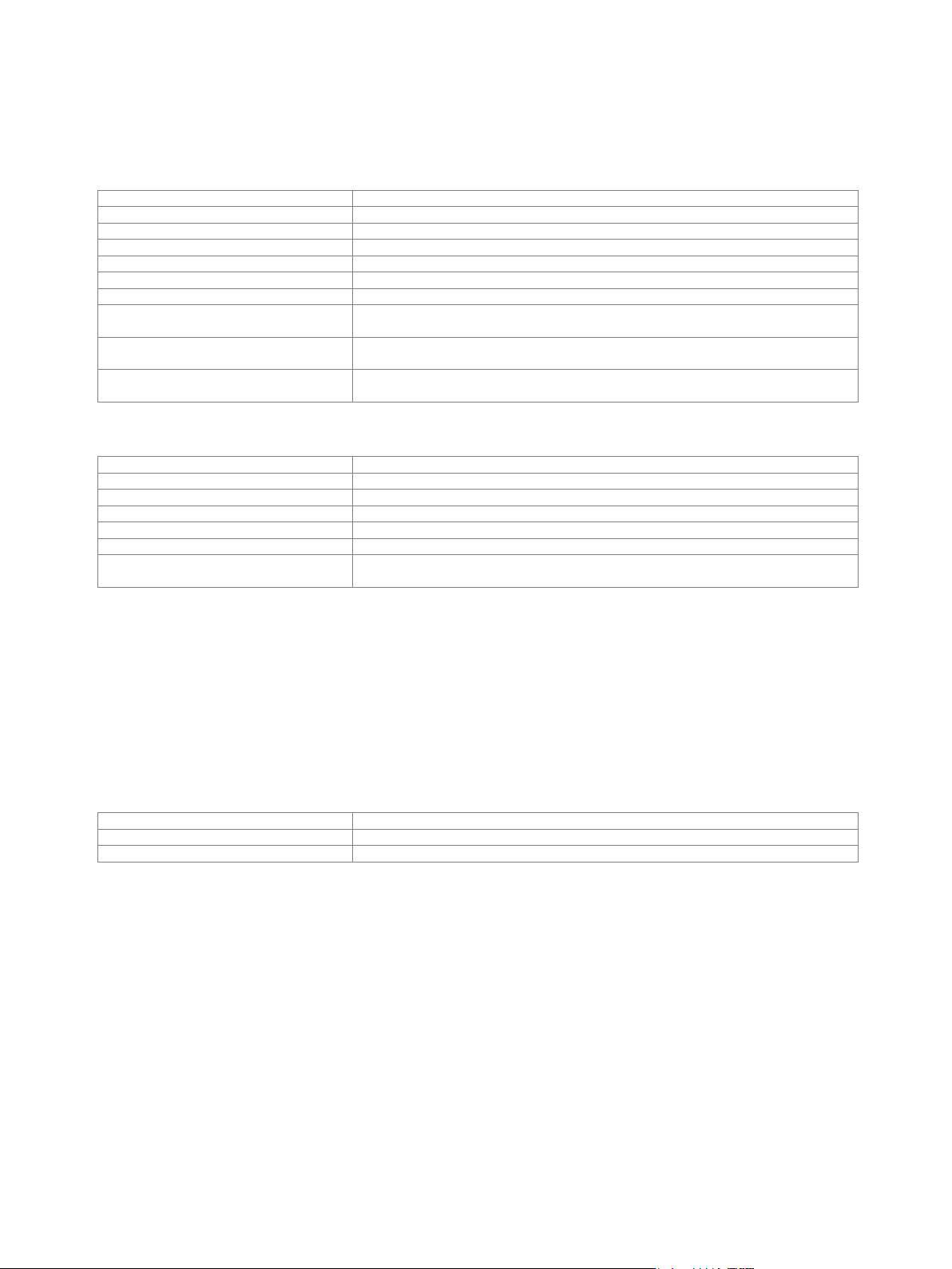
The following table shows the possible option combinations for instruments with two RF paths.
Phase noise performance level
Required options for RF path A
Required options for RF path B
Standard performance
R&S
®
SMW-B10xx frequency option
R&S
®
SMW-B20xx frequency option
Low phase noise
R&S
®
SMW-B10xx frequency option and
R&S
®
SMW-B709
R&S
®
SMW-B20xx frequency option and
R&S
®
SMW-B719
Improved close-in phase noise
performance
R&S
®
SMW-B10xx frequency option and
R&S
®
SMW-B710
R&S
®
SMW-B20xx frequency option and
R&S
®
SMW-B720
Ultra low phase noise
R&S
®
SMW-B10xx frequency option and
R&S
®
SMW-B711
R&S
®
SMW-B20xx frequency option and
R&S
®
SMW-B721
1
R&S
®
SMW-B1044 can only be combined with R&S
®
SMW-B2044, R&S
®
SMW-B1044N can only be combined with R&S
®
SMW-B2044N and
R&S
®
SMW-B1044O can only be combined with R&S
®
SMW-B2044O.