SMW200A_specs_en_3606-8037-22_v2700.pdf - 第27页
Version 27.00, October 2024 Rohde & Schwar z R&S ® SMW200A Vec tor Signal Generator 27 Phase coherence ( R&S ® SMW-B90 opti on) The R&S ® SMW-B90 option can be installed once, but can be used with all ins…
Version 27.00, October 2024
26 Rohde & Schwarz R&S
®
SMW200A Vector Signal Generator
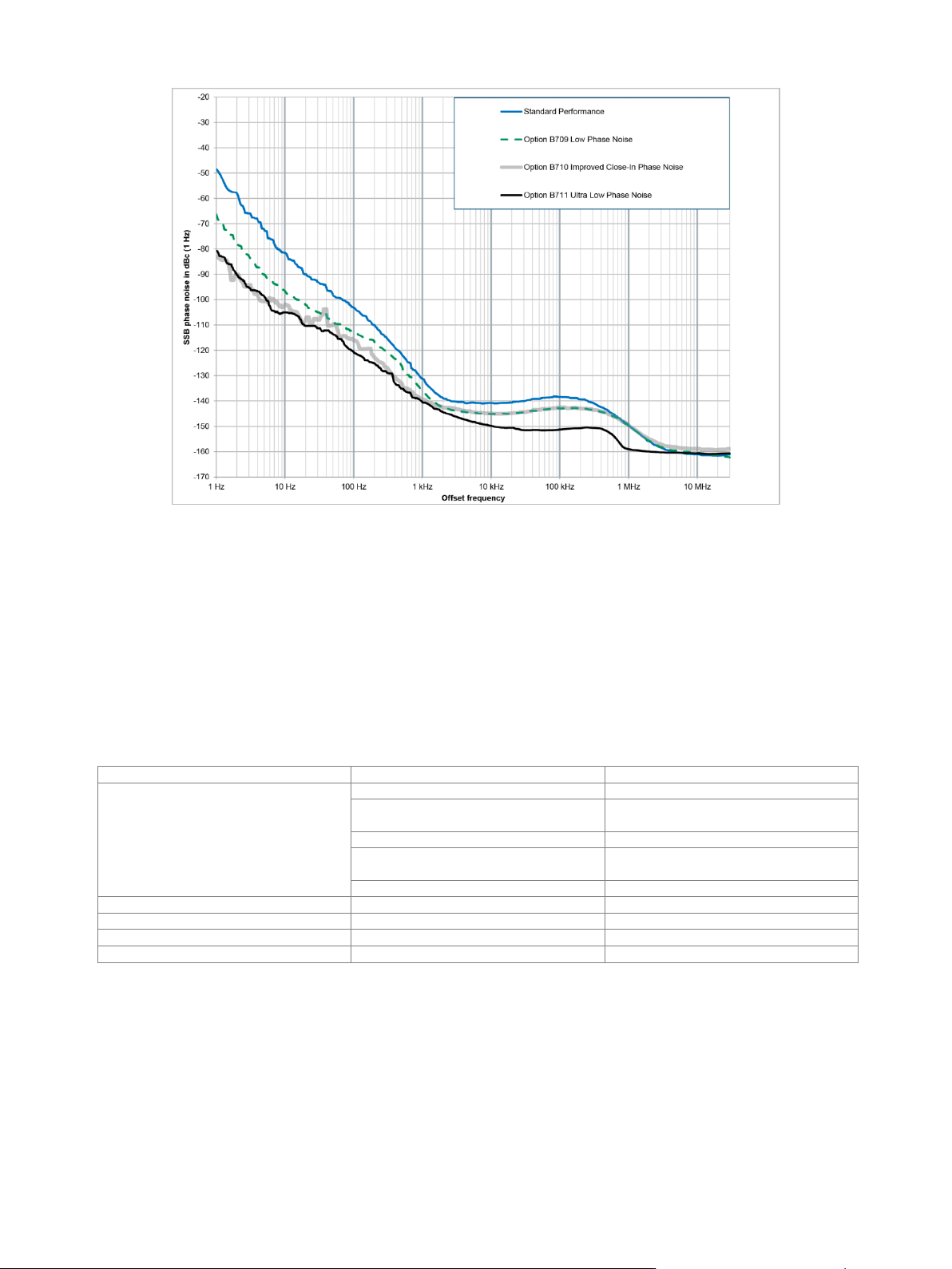
Measured SSB phase noise performance at f = 1 GHz, CW mode, standard performance versus the
R&S
®
SMW-B709, R&S
®
SMW-B710 and R&S
®
SMW-B711 options
List mode
Frequency and level values can be stored in a list and set in an extremely short amount of time, triggered by an internal timer or an
external trigger connector. There are two run modes available:
• Learned: faster (see frequency and level data), limited number of steps, cannot be combined with I/Q optimization mode
“high quality”, not available if the instrument is equipped with R&S
®
SMW-B711/-B721 ultra low phase noise options
• Live: works only for dwell times above 2 ms
Run modes
learned, live
Operating modes
internal trigger, infinite
automatic
internal trigger, one sweep per trigger
event
single
internal trigger, one step per trigger event
step
external trigger, one sweep per trigger
event
extern single
external trigger, one step per trigger event
extern step
Maximum number of steps (learned mode)
10000
Dwell time
can be set individually for each step
0.5 ms to 100 s
Resolution
0.1 ms
Setting time
after external trigger
see frequency and level data
Version 27.00, October 2024
Rohde & Schwarz R&S
®
SMW200A Vector Signal Generator 27
Phase coherence (R&S
®
SMW-B90 option)
The R&S
®
SMW-B90 option can be installed once, but can be used with all installed RF paths. It provides phase-coherent RF outputs
for the two RF paths or two or more instruments.
The option cannot be installed if an R&S
®
SMW-B1044O, R&S
®
SMW-B2044O, R&S
®
SMW-B1056O or R&S
®
SMW-B1067O option
is installed.
LO coupling modes
This mode corresponds to internal
LO operation in path A and path B.
A, B internal
This mode corresponds to internal
LO operation in path A, and LO of path B
is coupled to path A.
A internal,
A → B coupled
This mode corresponds to external
LO operation at the LO IN connector in
path A and internal LO operation in
path B.
A external,
B internal
This mode corresponds to external
LO operation at the REF/LO IN connector
in path A and path B.
A external,
A → B coupled
REF/LO OUT states
The active LO signal of path B can be
routed to the LO OUT connector (in order
to couple two or more instruments).
on/off
Input of phase coherence signal
Connector type
LO IN on rear panel
SMA female
Input impedance
50 Ω (nom.)
Input level range of external LO signal
7 dBm to 13 dBm
Frequency range of external LO signal
for RF setting 200 MHz < f ≤ 6.5 GHz
1.0 · f
for RF setting 6.5 GHz < f ≤ 13 GHz
0.5 · f
for RF setting 13 GHz < f ≤ 26 GHz
0.25 · f
for RF setting 26 GHz < f ≤ 44 GHz
0.125 · f
R&S
®
SMW-B1056, R&S
®
SMW-B1056N, R&S
®
SMW-B1067, R&S
®
SMW-B1067N
frequency options
for RF setting 43 GHz < f ≤ 65 GHz
0.1 · f
for RF setting 65 GHz < f ≤ 72 GHz
0.05 · f
Output of phase coherence signal
Connector type
LO OUT on rear panel
SMA female
Output impedance
50 Ω (nom.)
Output level range of internal LO signal
7 dBm to 13 dBm
Frequency range of internal LO signal
for RF setting 200 MHz < f ≤ 6.5 GHz
1.0 · f
for RF setting 6.5 GHz < f ≤ 13 GHz
0.5 · f
for RF setting 13 GHz < f ≤ 26 GHz
0.25 · f
for RF setting 26 GHz < f ≤ 44 GHz
0.125 · f
R&S
®
SMW-B1056, R&S
®
SMW-B1056N, R&S
®
SMW-B1067, R&S
®
SMW-B1067N
frequency options
for RF setting 43 GHz < f ≤ 65 GHz
0.1 · f
for RF setting 65 GHz < f ≤ 72 GHz
0.05 · f
Version 27.00, October 2024
28 Rohde & Schwarz R&S
®
SMW200A Vector Signal Generator
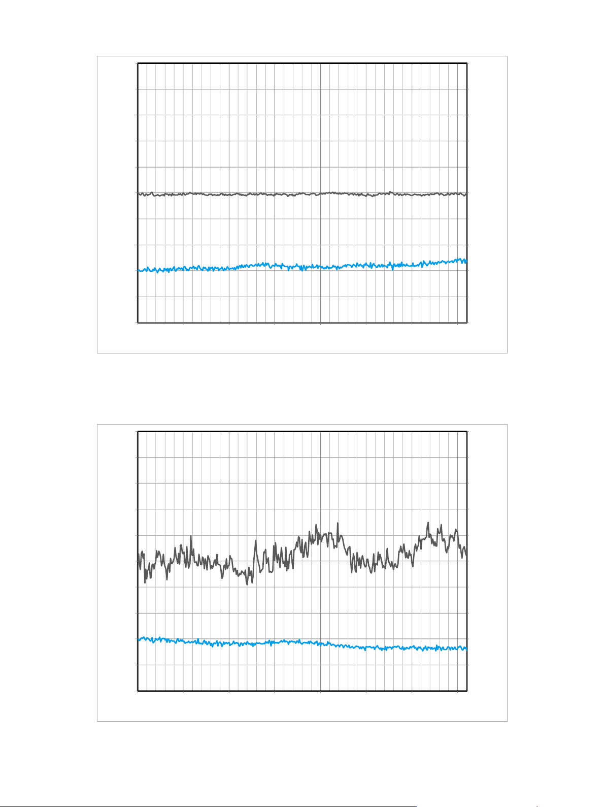
Measured relative phase between two LO coupled R&S
®
SMW200A RF paths versus time, carrier frequency = 2 GHz, level = –10 dBm
(the lower curve/right vertical axis indicates the temperature variation)
Measured relative phase between two LO coupled R&S
®
SMW200A RF paths versus time, carrier frequency = 40 GHz, level = –10 dBm
(the lower curve/right vertical axis indicates the temperature variation)
-0.20
-0.10
0.00
0.10
0.20
0.30
0.40
0.50
0.60
0.70
0.80
-1.00
-0.80
-0.60
-0.40
-0.20
0.00
0.20
0.40
0.60
0.80
1.00
0 500 1000 1500 2000 2500 3000 3500
Relative temperature /
°C
Relative phase /
°
Time / s
-0.20
-0.10
0.00
0.10
0.20
0.30
0.40
0.50
0.60
0.70
0.80
-1.00
-0.80
-0.60
-0.40
-0.20
0.00
0.20
0.40
0.60
0.80
1.00
0 500 1000 1500 2000 2500 3000 3500
Relative temperature /
°C
Relative phase /
°
Time / s