SMW200A_specs_en_3606-8037-22_v2700.pdf - 第14页
Version 27.00, October 2024 14 Rohde & Schwar z R&S ® SMW200A Vec tor Signal Generator Level error level setting chara cteristic: auto, tempe rature range from +18 °C to +33 °C 100 kHz ≤ f ≤ 3 GHz < 0.5 dB 3 G…
Version 27.00, October 2024
Rohde & Schwarz R&S
®
SMW200A Vector Signal Generator 13
In NARROW mode, the reference PLL acts as a clean-up-loop in which the phase noise is mainly determined by the signal generator’s
internal reference source.
This mode is recommended when using external reference sources with close-to-carrier phase noise worse than the R&S
®
SMW200A
(i. e. rubidium standards).
Note that due to the slow synchronization, reference locking can take up to 10 s.
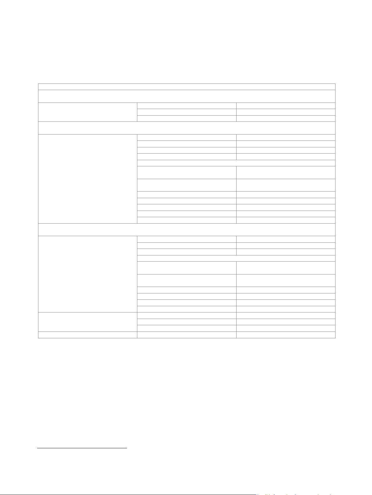
Level
Specified level range
With R&S
®
SMW-B1003, R&S
®
SMW-B2003, R&S
®
SMW-B1006, R&S
®
SMW-B2006, R&S
®
SMW-B1007, R&S
®
SMW-B2007,
R&S
®
SMW-B1012, R&S
®
SMW-B2012, R&S
®
SMW-B1020, R&S
®
SMW-B2020 frequency options
100 kHz ≤ f < 1 MHz
–120 dBm to +3 dBm (PEP)
2
1 MHz ≤ f ≤ 3 MHz
–120 dBm to +8 dBm (PEP)
2
3 MHz < f ≤ 20 GHz
–120 dBm to +18 dBm (PEP)
2
With R&S
®
SMW-B1031, R&S
®
SMW-B2031, R&S
®
SMW-B1040, R&S
®
SMW-B1040N, R&S
®
SMW-B1044, R&S
®
SMW-B2044,
R&S
®
SMW-B1044N, R&S
®
SMW-B2044N, R&S
®
SMW-B1044O, R&S
®
SMW-B2044O frequency options
100 kHz ≤ f < 1 MHz
–120 dBm to +3 dBm (PEP)
2
1 MHz ≤ f ≤ 3 MHz
–120 dBm to +8 dBm (PEP)
2
3 MHz < f ≤ 3 GHz
–120 dBm to +18 dBm (PEP)
2
3 GHz < f ≤ 14 GHz
–120 dBm to +17 dBm (PEP)
2
14 GHz < f ≤ 20 GHz
CW, I/Q modulation,
signal bandwidth ≤ 160 MHz
–120 dBm to +15 dBm (PEP)
2
I/Q modulation,
signal bandwidth > 160 MHz
–120 dBm to +12 dBm (PEP)
2
20 GHz < f ≤ 29 GHz
–120 dBm to +18 dBm (PEP)
2
29 GHz < f ≤ 33 GHz
–120 dBm to +17 dBm (PEP)
2
33 GHz < f ≤ 40 GHz
–120 dBm to +15 dBm (PEP)
2
40 GHz < f ≤ 42 GHz
–120 dBm to +13 dBm (PEP)
2
42 GHz < f ≤ 44 GHz
–120 dBm to +12 dBm (PEP)
2
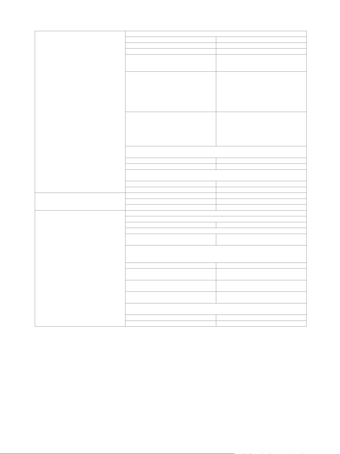
With R&S
®
SMW-B1056, R&S
®
SMW-B1056N, R&S
®
SMW-B1056O, R&S
®
SMW-B1067, R&S
®
SMW-B1067N, R&S
®
SMW-B1067O
frequency options
100 kHz ≤ f < 1 MHz
–120 dBm to +3 dBm (PEP)
2
1 MHz ≤ f ≤ 3 MHz
–120 dBm to +8 dBm (PEP)
2
3 MHz < f ≤ 16 GHz
–120 dBm to +15 dBm (PEP)
2
16 GHz < f ≤ 20 GHz
CW, I/Q modulation,
signal bandwidth ≤ 160 MHz
–120 dBm to +13 dBm (PEP)
2
I/Q modulation,
signal bandwidth > 160 MHz
–120 dBm to +10 dBm (PEP)
2
20 GHz < f ≤ 33 GHz
–120 dBm to +15 dBm (PEP)
2
33 GHz < f ≤ 43 GHz
–115 dBm to +10 dBm (PEP)
2
43 GHz < f ≤ 60 GHz
–115 dBm to +12 dBm (PEP)
2
60 GHz < f ≤ 67 GHz
–115 dBm to +10 dBm (PEP)
2
Setting range
100 kHz ≤ f < 1 MHz
–145 dBm to +8 dBm
1 MHz ≤ f < 3 MHz
–145 dBm to +13 dBm
3 MHz ≤ f ≤ 67 GHz
–145 dBm to +30 dBm
Resolution of setting
0.01 dB (nom.)
2
PEP = peak envelope power.
Version 27.00, October 2024
14 Rohde & Schwarz R&S
®
SMW200A Vector Signal Generator
Level error
level setting characteristic: auto, temperature range from +18 °C to +33 °C
100 kHz ≤ f ≤ 3 GHz
< 0.5 dB
3 GHz < f ≤ 6 GHz
< 0.7 dB
6 GHz < f ≤ 20 GHz
< 0.9 dB
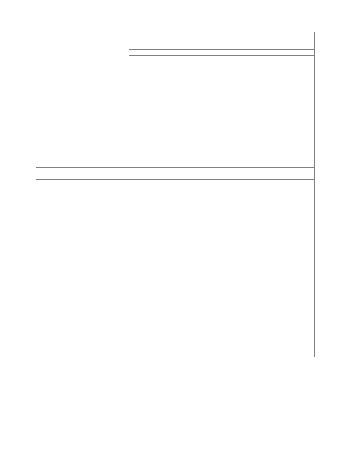
R&S
®
SMW-B1031, R&S
®
SMW-B2031,
R&S
®
SMW-B1040, R&S
®
SMW-B1040N,
20 GHz < f ≤ 40 GHz
< 1.1 dB
R&S
®
SMW-B1044,
R&S
®
SMW-B2044,
R&S
®
SMW-B1044N,
R&S
®
SMW-B2044N,
R&S
®
SMW-B1044O,
R&S
®
SMW-B2044O,
20 GHz < f ≤ 44 GHz
< 1.2 dB
R&S
®
SMW-B1056,
R&S
®
SMW-B1056N,
R&S
®
SMW-B1056O,
R&S
®
SMW-B1067, R&S
®
SMW-B1067N,
R&S
®
SMW-B1067O,
20 GHz < f ≤ 43 GHz
< 1.1 dB
R&S
®
SMW-B1056, R&S
®
SMW-B1056N, R&S
®
SMW-B1056O,
43 GHz < f ≤ 56 GHz
level ≥ –90 dBm
< 1.2 dB
level < –90 dBm
< 1.5 dB
R&S
®
SMW-B1067, R&S
®
SMW-B1067N, R&S
®
SMW-B1067O,
43 GHz < f ≤ 67 GHz
level ≥ –90 dBm
< 1.2 dB
level < –90 dBm
< 1.5 dB
Additional level error
I/Q modulation
optimization mode: high quality, fast
< 0.3 dB
pulse modulation
< 0.5 dB
Output impedance, VSWR in 50 Ω system
ALC state: on
R&S
®
SMW-B1003, R&S
®
SMW-B2003, R&S
®
SMW-B1006, R&S
®
SMW-B2006
100 kHz < f ≤ 6 GHz
< 1.9, < 1.5 (typ.)
R&S
®
SMW-B1007, R&S
®
SMW-B2007, R&S
®
SMW-B1012, R&S
®
SMW-B2012,
100 kHz < f ≤ 12.75 GHz
< 2.0, < 1.6 (typ.)
R&S
®
SMW-B1020, R&S
®
SMW-B2020, R&S
®
SMW-B1031, R&S
®
SMW-B2031,
R&S
®
SMW-B1040, R&S
®
SMW-B1040N, R&S
®
SMW-B1044, R&S
®
SMW-B2044,
R&S
®
SMW-B1044N, R&S
®
SMW-B2044N, R&S
®
SMW-B1044O, R&S
®
SMW-B2044O
100 kHz < f ≤ 20 GHz
< 2.1, < 1.7 (typ.)
step attenuator = 0 dB,
20 GHz < f ≤ 38 GHz
< 2.2, < 1.8 (typ.)
step attenuator = 0 dB,
38 GHz < f ≤ 44 GHz
< 2.6, < 2.2 (typ.)
step attenuator ≥ 5 dB,
20 GHz < f ≤ 44 GHz
< 2.1, < 1.7 (typ.)
R&S
®
SMW-B1056, R&S
®
SMW-B1056N, R&S
®
SMW-B1056O,
R&S
®
SMW-B1067, R&S
®
SMW-B1067N, R&S
®
SMW-B1067O
100 kHz < f ≤ 38 GHz
< 2.2, < 1.8 (typ.)
38 GHz < f ≤ 50 GHz
< 2.6, < 2.2 (typ.)
Version 27.00, October 2024
Rohde & Schwarz R&S
®
SMW200A Vector Signal Generator 15
Setting time
to < 0.1 dB deviation from final value, with GUI update stopped, no relay switchover,
f > 10 MHz, I/Q optimization mode: fast, health and utilization monitoring service
(HUMS) off
after IEC/IEEE bus delimiter
3
< 1.2 ms, 1 ms (typ.)
with switching of mechanical step
attenuator, after IEC/IEEE bus delimiter
< 25 ms
R&S
®
SMW-B1044, R&S
®
SMW-B1044N,
R&S
®
SMW-B1044O,
R&S
®
SMW-B2044, R&S
®
SMW-B2044N,
R&S
®
SMW-B2044O,
R&S
®
SMW-B1056, R&S
®
SMW-B1056N,
R&S
®
SMW-B1056O,
R&S
®
SMW-B1067, R&S
®
SMW-B1067N,
R&S
®
SMW-B1067O,
with switching of mechanical step
attenuator,
after IEC/IEEE bus delimiter
< 30 ms
Setting time (list mode)
to < 0.1 dB deviation from final value, with GUI update stopped, no relay switchover,
f > 10 MHz, I/Q optimization mode: fast, health and utilization monitoring service
(HUMS) off
after trigger pulse
3
< 0.8 ms, 0.55 ms (typ.)
with R&S
®
SMW-B711,
R&S
®
SMW-B721, run mode: live
< 1 ms
Interruption-free level setting range
level setting characteristic:
uninterrupted level setting
> 20 dB
Reverse power (from 50 Ω source)
maximum permissible RF power in output frequency range of RF path with
R&S
®
SMW-B1003, R&S
®
SMW-B2003, R&S
®
SMW-B1006, R&S
®
SMW-B2006
frequency options;
Note: The RF path is switched off if the reverse power exceeds a limit
(+27 dBm (meas.), depends on RF frequency).
1 MHz < f ≤ 3 GHz
50 W
3 GHz < f ≤ 6 GHz
10 W
maximum permissible RF power in output frequency range of RF path with
R&S
®
SMW-B1007, R&S
®
SMW-B2007, R&S
®
SMW-B1012, R&S
®
SMW-B1020,
R&S
®
SMW-B2020, R&S
®
SMW-B1031, R&S
®
SMW-B2031, R&S
®
SMW-B1040,
R&S
®
SMW-B1040N, R&S
®
SMW-B1044, R&S
®
SMW-B2044, R&S
®
SMW-B1044N,
R&S
®
SMW-B2044N, R&S
®
SMW-B1044O, R&S
®
SMW-B2044O, R&S
®
SMW-B1056,
R&S
®
SMW-B1056N, R&S
®
SMW-B1056O, R&S
®
SMW-B1067, R&S
®
SMW-B1067N,
R&S
®
SMW-B1067O frequency options
1 MHz < f ≤ 67 GHz
0.5 W
Maximum permissible DC voltage
R&S
®
SMW-B1003, R&S
®
SMW-B2003,
R&S
®
SMW-B1006, R&S
®
SMW-B2006
frequency options
50 V
R&S
®
SMW-B1007, R&S
®
SMW-B2007,
R&S
®
SMW-B1012, R&S
®
SMW-B2012
frequency options
35 V
R&S
®
SMW-B1020, R&S
®
SMW-B2020,
R&S
®
SMW-B1031, R&S
®
SMW-B1040,
R&S
®
SMW-B1040N, R&S
®
SMW-B1044,
R&S
®
SMW-B2044, R&S
®
SMW-B1044N,
R&S
®
SMW-B2044N, R&S
®
SMW-B1044O,
R&S
®
SMW-B2044O, R&S
®
SMW-B1056,
R&S
®
SMW-B1056N, R&S
®
SMW-B1056O,
R&S
®
SMW-B1067, R&S
®
SMW-B1067N,
R&S
®
SMW-B1067O frequency options
0 V
3
R&S
®
SMW-B1007, R&S
®
SMW-B2007, R&S
®
SMW-B1012, R&S
®
SMW-B1020, R&S
®
SMW-B2020, R&S
®
SMW-B1031, R&S
®
SMW-B1040,
R&S
®
SMW-B1040N: temperature > +18 °C.