SMW200A_specs_en_3606-8037-22_v2700.pdf - 第71页
Version 27.00, October 2024 Rohde & Schwar z R&S ® SMW200A Vec tor Signal Generator 71 Signal performa nce for digital standards a nd modulation systems 5G NR ( R&S ® SMW- K144 option) Error vector magn itude…
Version 27.00, October 2024
70 Rohde & Schwarz R&S
®
SMW200A Vector Signal Generator
BER measurement (R&S
®
SMW-K80 option)
At least one R&S
®
SMW-B10 standard baseband generator option or R&S
®
SMW-B9 wideband baseband generator option must be
installed.
The data supplied by the DUT is compared with a reference pseudo-random bit sequence.
Clock
supplied by DUT; a clock pulse is required
for each valid bit
Clock rate
100 Hz to 100 MHz
Data
PRBS
sequence length
9, 11, 15, 16, 20, 21, 23
pattern ignore
off, All 0, All 1
data enable
external
modes
off, high, low
restart
external
modes
on/off
Synchronization time
28 clock cycles
Interface
4 BNC connectors, selectable from USER 1 to 6
Clock, data, enable and restart inputs
input impedance
1 kΩ, 50 Ω
trigger threshold
setting range
0.1 V to 2.0 V
setting resolution
0.1 V
Polarity
data, clock, data enable
normal, inverted
Measurement time
selectable by means of maximum number
of data bits or bit errors (max. 2
31
bit
each), continuous measurement
Measurement result
if selected number of data bits or bit errors
is attained
BER in ppm, % or decade values
Status displays
not synchronized, no clock, no data
BLER measurement (R&S
®
SMW-K80 option)
At least one R&S
®
SMW-B10 standard baseband generator option or R&S
®
SMW-B9 wideband baseband generator option must be
installed.
In BLER measurement mode, arbitrary data can be provided by the DUT. A signal marking the block’s CRC has to be provided on the
data enable connector of the BER/BLER option.
Clock
supplied by DUT; a clock pulse is required
for each valid bit
Clock rate
100 Hz to 100 MHz
Data
input data
arbitrary
data enable (marking the block’s CRC)
external
modes
high, low
CRC
CRC type
CCITT CRC16 (x
16
+ x
12
+ x
5
+ 1)
CRC bit order
MSB first, LSB first
Synchronization time
1 block
Interface
4 BNC connectors, selectable from USER 1 to 6
Clock, data, and enable inputs
input impedance
1 kΩ, 50 Ω
trigger threshold
setting range
0.1 V to 2.0 V
setting resolution
0.1 V
Polarity
data, clock, data enable
normal, inverted
Measurement time
selectable by means of maximum number of received blocks or errors (max. 2
31
blocks
each), continuous measurement
Measurement result
if selected number of received blocks or
errors is attained
BLER in ppm, % or decade values
Status displays
not synchronized, no clock, no data
Version 27.00, October 2024
Rohde & Schwarz R&S
®
SMW200A Vector Signal Generator 71
Signal performance for digital standards and modulation
systems
5G NR (R&S
®
SMW-K144 option)
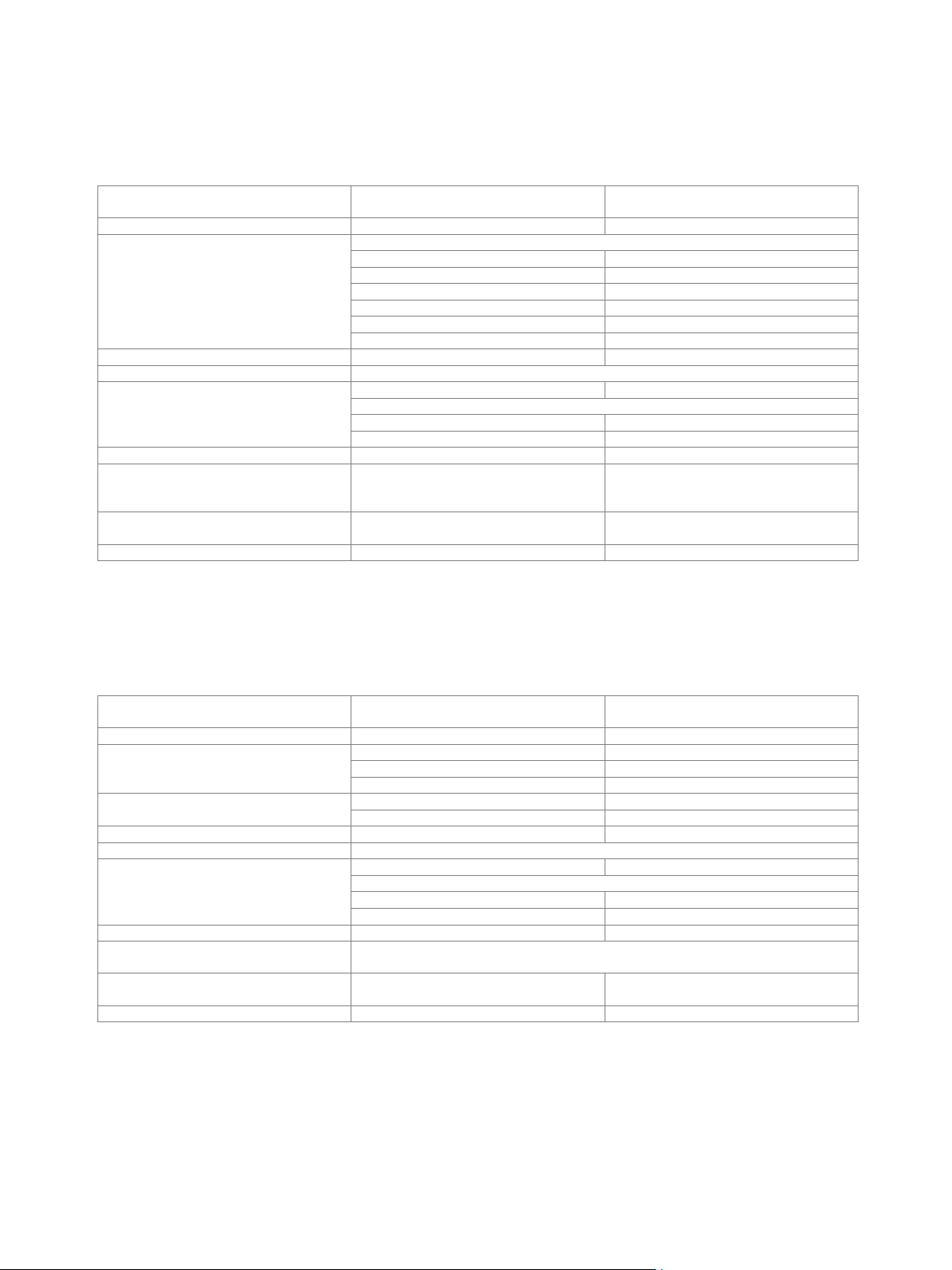
Error vector magnitude
Measured EVM versus carrier frequency for 5G NR, 100 MHz, linearize RF active
Measured EVM versus output power at f = 3.4 GHz for 5G NR, 100 MHz, 64QAM, 60 kHz SCS, linearize RF active
0.00
0.25
0.50
0.75
1.00
1.25
1.50
0 5 10 15 20 25 30 35 40 45 50 55 60 65
EVM (rms) / %
Carrier Frequency / GHz
0 dBm
5 dBm
0
0.2
0.4
0.6
0.8
1
1.2
1.4
-30 -25 -20 -15 -10 -5 0 5 10
EVM / %
Output Power / dBm
3.4 GHz
Version 27.00, October 2024
72 Rohde & Schwarz R&S
®
SMW200A Vector Signal Generator
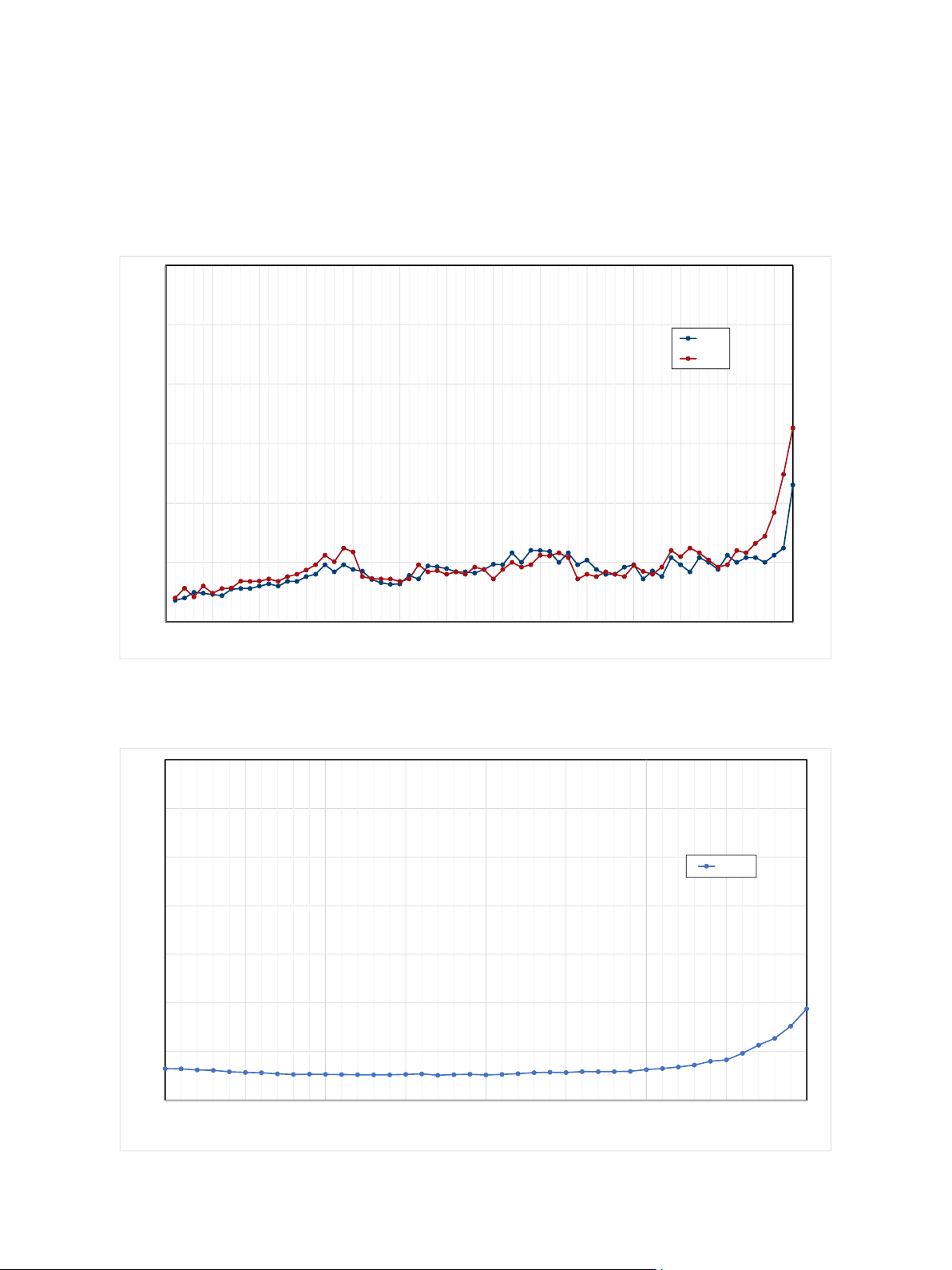
Measured EVM versus output power at f = 13 GHz for 5G NR, 200 MHz, 64QAM, 60 kHz SCS, linearize RF active
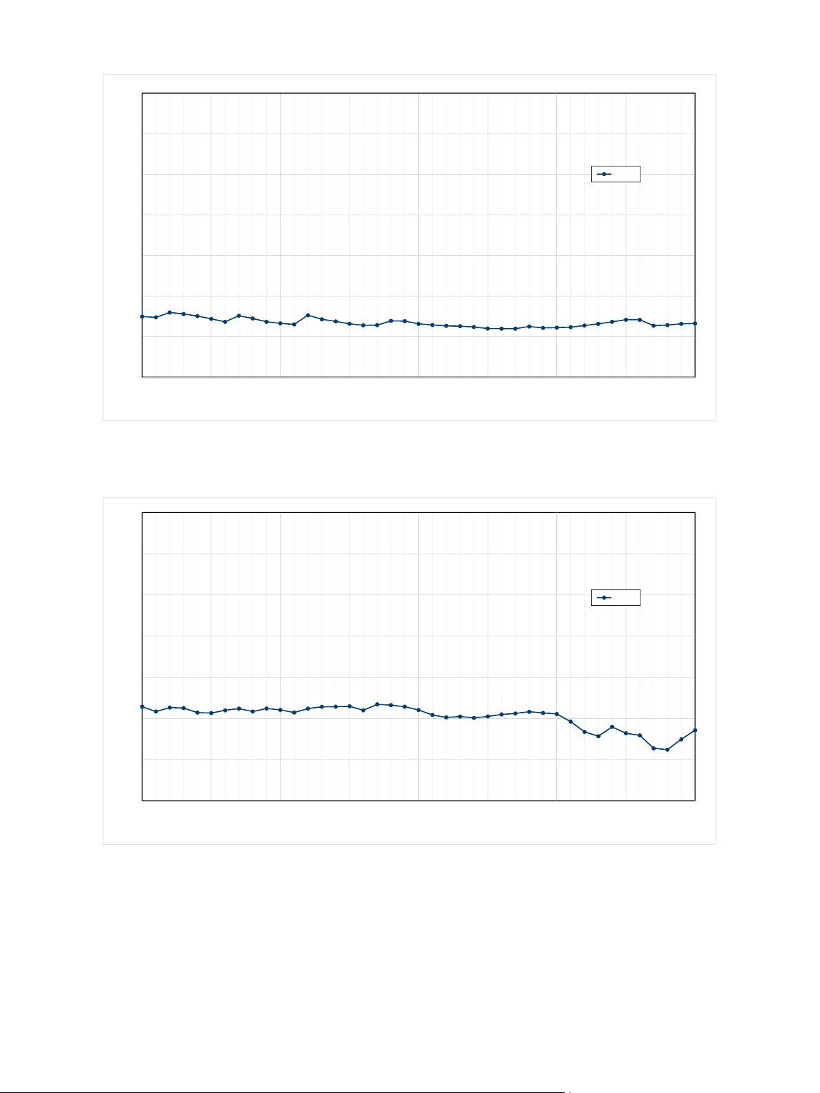
Measured EVM versus output power at f = 28 GHz for 5G NR, 400 MHz, 64 QAM, 120 kHz SCS, linearize RF active
0
0.2
0.4
0.6
0.8
1
1.2
1.4
-30 -25 -20 -15 -10 -5 0 5 10
EVM / %
Output Power / dBm
13 GHz
0
0.2
0.4
0.6
0.8
1
1.2
1.4
-30 -25 -20 -15 -10 -5 0 5 10
EVM / %
Output Power / dBm
28 GHz