SMW200A_specs_en_3606-8037-22_v2700.pdf - 第7页
Version 27.00, October 2024 Rohde & Schwar z R&S ® SMW200A Vec tor Signal Generator 7 Frequency and baseband main module options Frequency options One of the following frequency opt ions must be installed in RF p…
Version 27.00, October 2024
6 Rohde & Schwarz R&S
®
SMW200A Vector Signal Generator
Definitions
General
Product data applies under the following conditions:
• Three hours of storage at ambient temperature followed by 30 minutes of warm-up operation
• Specified environmental conditions met
• Recommended calibration interval adhered to
• All internal automatic adjustments performed, if applicable
Specifications with limits
Represent warranted product performance by means of a range of values for the specified parameter. These specifications are
marked with limiting symbols such as <, ≤, >, ≥, ±, or descriptions such as maximum, limit of, minimum. Compliance is ensured by
testing or is derived from the design. Test limits are narrowed by guard bands to take into account measurement uncertainties, drift
and aging, if applicable.
Non-traceable specifications with limits (n. trc.)
Represent product performance that is specified and tested as described under Specifications with limits above. However, product
performance in this case cannot be warranted due to the lack of measuring equipment traceable to national metrology standards. In
this case, measurements are referenced to standards used in the Rohde & Schwarz laboratories.
Specifications without limits
Represent warranted product performance for the specified parameter. These specifications are not specially marked and represent
values with no or negligible deviations from the given value (e.g. dimensions or resolution of a setting parameter). Compliance is
ensured by design.
Typical data (typ.)
Characterizes product performance by means of representative information for the given parameter. When marked with <, > or as a
range, it represents the performance met by approximately 80 % of the instruments at production time. Otherwise, it represents the
mean value.
Nominal values (nom.)
Characterize product performance by means of a representative value for the given parameter (e.g. nominal impedance). In contrast to
typical data, a statistical evaluation does not take place and the parameter is not tested during production.
Measured values (meas.)
Characterize expected product performance by means of measurement results gained from individual samples.
Uncertainties
Represent limits of measurement uncertainty for a given measurand. Uncertainty is defined with a coverage factor of 2 and has been
calculated in line with the rules of the Guide to the Expression of Uncertainty in Measurement (GUM), taking into account
environmental conditions, aging, wear and tear.
Device settings and GUI parameters are designated with the format “parameter: value”.
Non-traceable specifications with limits, typical data as well as nominal and measured values are not warranted by Rohde & Schwarz.
In line with the 3GPP standard, chip rates are specified in million chips per second (Mcps), whereas bit rates and symbol rates are
specified in billion bit per second (Gbps), million bit per second (Mbps), thousand bit per second (kbps), million symbols per second
(Msps) or thousand symbols per second (ksps), and sample rates are specified in million samples per second (Msample/s). Gbps,
Mcps, Mbps, Msps, kbps, ksps and Msample/s are not SI units.
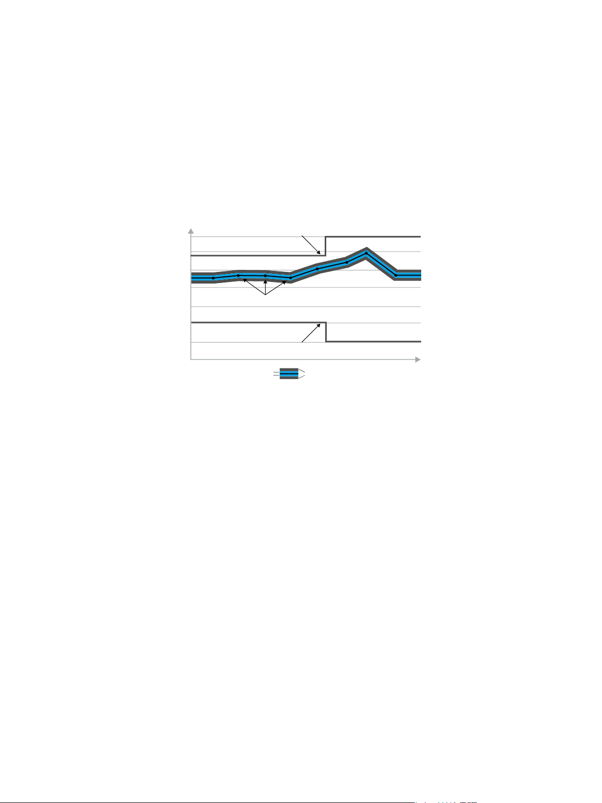
X-axis
Y-axis
Specification limit
Actual values with measurement uncertainty and guard band
Specification limit
Measurement uncertainties Guard band
Version 27.00, October 2024
Rohde & Schwarz R&S
®
SMW200A Vector Signal Generator 7
Frequency and baseband main module options
Frequency options
One of the following frequency options must be installed in RF path A:
R&S
®
SMW-B1003
100 kHz to 3 GHz
R&S
®
SMW-B1006
100 kHz to 6 GHz
R&S
®
SMW-B1007
100 kHz to 7.5 GHz
R&S
®
SMW-B1012
100 kHz to 12.75 GHz
R&S
®
SMW-B1020
100 kHz to 20 GHz
R&S
®
SMW-B1031
100 kHz to 31.8 GHz
R&S
®
SMW-B1040, R&S
®
SMW-B1040N
100 kHz to 40 GHz
R&S
®
SMW-B1044, R&S
®
SMW-B1044N,
R&S
®
SMW-B1044O
100 kHz to 44 GHz
R&S
®
SMW-B1056, R&S
®
SMW-B1056N,
R&S
®
SMW-B1056O
100 kHz to 56 GHz
R&S
®
SMW-B1067, R&S
®
SMW-B1067N,
R&S
®
SMW-B1067O
100 kHz to 67 GHz
In addition, one of the following frequency options can be installed in RF path B:
R&S
®
SMW-B2003
100 kHz to 3 GHz
R&S
®
SMW-B2006
100 kHz to 6 GHz
R&S
®
SMW-B2007
100 kHz to 7.5 GHz
R&S
®
SMW-B2012
100 kHz to 12.75 GHz
R&S
®
SMW-B2020
100 kHz to 20 GHz
R&S
®
SMW-B2031
100 kHz to 31.8 GHz
R&S
®
SMW-B2044, R&S
®
SMW-B2044N,
R&S
®
SMW-B2044O
100 kHz to 44 GHz
The R&S
®
SMW-B1003, R&S
®
SMW-B2003, R&S
®
SMW-B1006, R&S
®
SMW-B2006, R&S
®
SMW-B1007, R&S
®
SMW-B2007,
R&S
®
SMW-B1012 and R&S
®
SMW-B2012 options include an electronic attenuator, whereas the R&S
®
SMW-B1020,
R&S
®
SMW-B2020, R&S
®
SMW-B1031, R&S
®
SMW-B2031, R&S
®
SMW-B1040, R&S
®
SMW-B1040N, R&S
®
SMW-B1044,
R&S
®
SMW-B2044, R&S
®
SMW-B1044N, R&S
®
SMW-B1044O, R&S
®
SMW-B2044N, R&S
®
SMW-B2044O, R&S
®
SMW-B1056,
R&S
®
SMW-B1056N, R&S
®
SMW-B1056O, R&S
®
SMW-B1067, R&S
®
SMW-B1067N and R&S
®
SMW-B1067O options include a
mechanical step attenuator.
For possible RF path combinations, see section Frequency options and RF path combinations.
Signal routing and baseband main module options
One of the following options must be installed:
R&S
®
SMW-B13
one I/Q path to RF section
R&S
®
SMW-B13T
two I/Q paths to RF section
R&S
®
SMW-B13XT
wideband, two I/Q paths to RF section
If RF path B is equipped with an R&S
®
SMW-B20xx frequency option, an R&S
®
SMW-B13T or R&S
®
SMW-B13XT option must be
installed as the baseband main module.
R&S
®
SMW-B13 and R&S
®
SMW-B13T cannot be installed in instruments equipped with R&S
®
SMW-B1044O, R&S
®
SMW-B2044O,
R&S
®
SMW-B1056O or R&S
®
SMW-B1067O frequency options.

Version 27.00, October 2024
8 Rohde & Schwarz R&S
®
SMW200A Vector Signal Generator
Baseband hardware overview
To select between two different baseband sections, simply choose the appropriate baseband main module.
To select the standard baseband section, choose the R&S
®
SMW-B13 or R&S
®
SMW-B13T option as the baseband main module. The
standard baseband section enables RF modulation bandwidths up to 160 MHz and allows further options for fading and MIMO to be
installed. It provides the following additional hardware options:
R&S
®
SMW-B10
standard baseband generator
R&S
®
SMW-B14
fading simulator
To select the wideband baseband section, choose the R&S
®
SMW-B13XT option as the baseband main module. The wideband
baseband section enables RF modulation bandwidths up to 2 GHz and allows further options for fading and MIMO to be installed.
It provides the following additional hardware options:
R&S
®
SMW-B9
wideband baseband generator
R&S
®
SMW-B9F
wideband baseband generator for GNSS with high dynamics
R&S
®
SMW-B15
fading simulator and signal processor