SMW200A_specs_en_3606-8037-22_v2700.pdf - 第80页
Version 27.00, October 2024 80 Rohde & Schwar z R&S ® SMW200A Vec tor Signal Generator General data Power rating Rated voltage 100 V to 240 V AC Rated current with R&S ® SMW-B13/-B13T options 7.3 A to 4.6 A w…
Version 27.00, October 2024
Rohde & Schwarz R&S
®
SMW200A Vector Signal Generator 79
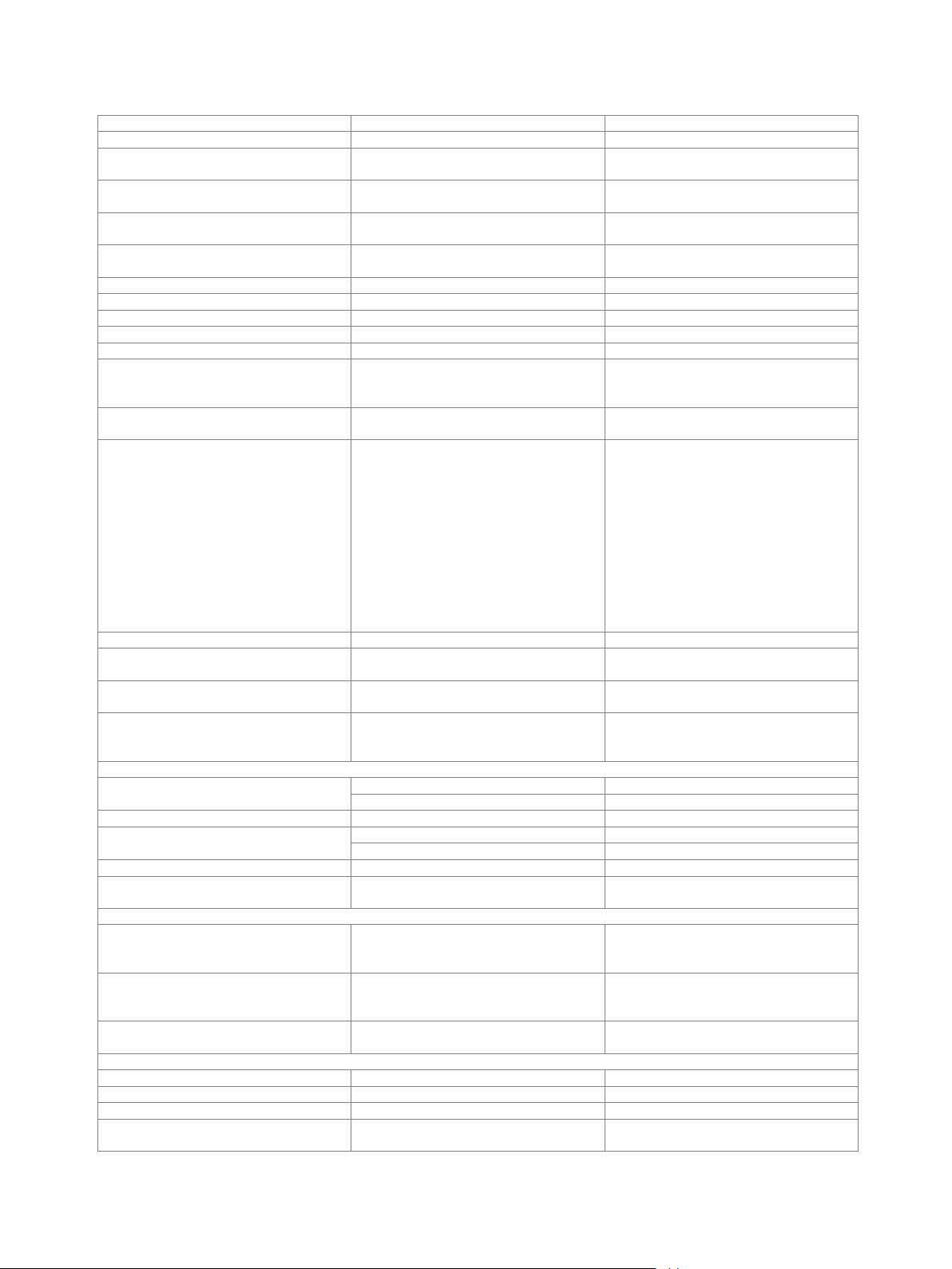
Rear panel connectors
REF IN
reference frequency input
BNC female
REF OUT
reference frequency output
BNC female
INST TRG A
trigger input for RF path A,
e.g. for frequency or level sweep
BNC female
INST TRG B
trigger input for RF path B,
e.g. for frequency or level sweep
BNC female
USER 4, USER 5, USER 6
user-configurable inputs or outputs,
e.g. as trigger input or marker output
BNC female
EFC
input for electronic tuning of internal
reference frequency
BNC female
LO IN
phase-coherent LO input
SMA female
LO OUT
phase-coherent LO output
SMA female
IEEE 488
remote control of instrument via GPIB
24-pin Amphenol series 57 female
DISPLAY PORT
for future use
HDMI
for future use
LAN
provides remote control functionality and
other services, see section Remote
control
RJ-45
USB DEVICE
USB 3.0 (super speed) remote control of
instrument (USB-TMC)
USB type B
USB
USB 3.1 (10 Gbit/s super speed ports)
connector for external USB devices such
as mouse and keyboard for enhanced
operation,
R&S
®
NRP-Zxx power sensors (with
R&S
®
NRP-ZKU USB interface cable) for
external power measurements and level
adjustment of instrument,
memory stick for software update and
data exchange,
USB serial adapter for RS-232 remote
control
USB type A
IEEE 488
remote control of instrument via GPIB
24-pin Amphenol series 57 female
EXT 1, EXT 2
inputs for external analog modulation
signals
BNC female
DIG I/Q OUT 1, DIG I/Q OUT 2
digital output connectivity in line with
R&S
®
Digital I/Q Interface
26-pin MDR
HS DIG I/Q OUT 1, HS DIG I/Q OUT 2
high speed digital output connectivity in
line with R&S
®
Digital I/Q Interface
(R&S
®
SMW-B13XT only)
QSFP+/QSFP 28
Analog I/Q outputs
I/LF OUT 1
analog I output
BNC female
alternative function: LF generator output
I 1
analog I-bar output
BNC female
Q/LF OUT 2
analog Q output
BNC female
alternative function: LF generator output
Q 1
analog Q-bar output
BNC female
I, I, Q, Q
second set of analog I, I-bar, Q, Q-bar
outputs
BNC female
Connectors on standard baseband generator and fading simulator modules
T/M/C 1, T/M/C 4
multipurpose input/output connectors;
configurable as trigger input, marker
output or clock input or output
BNC female
T/M 2, T/M 3, T/M 5, T/M 6
multipurpose input/output connectors;
configurable as trigger input or marker
output
BNC female
DIG IQ IN/OUT 1, DIG IQ IN/OUT 2
digital input or output connectivity in line
with R&S
®
Digital I/Q Interface
26-pin MDR
Connectors on wideband baseband generator modules
T/M/C 1, T/M/C 3
for future use
BNC female
T/M 2, T/M 4
for future use
BNC female
DIG IQ IN/OUT 1, DIG IQ IN/OUT 2
for future use
26-pin MDR
HS DIG IQ IN/OUT 1,
HS DIG IQ IN/OUT 2
high-speed digital input connectivity in line
with R&S
®
Digital I/Q Interface
QSFP+/QSFP 28
Version 27.00, October 2024
80 Rohde & Schwarz R&S
®
SMW200A Vector Signal Generator
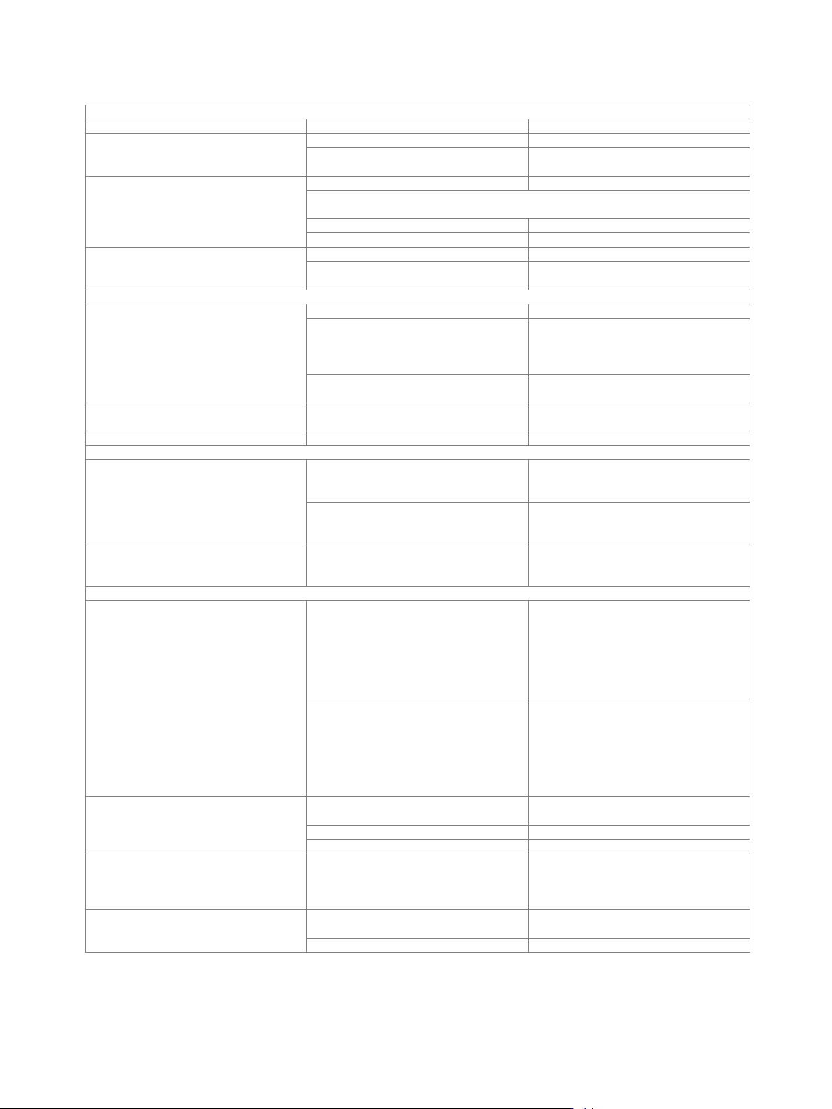
General data
Power rating
Rated voltage
100 V to 240 V AC
Rated current
with R&S
®
SMW-B13/-B13T options
7.3 A to 4.6 A
with R&S
®
SMW-B13XT or
R&S
®
SMW-B94L options
8.9 A to 4.9 A
Rated frequency
with R&S
®
SMW-B13/-B13T options
50 Hz to 60 Hz, 400 Hz
with R&S
®
SMW-B13XT or
R&S
®
SMW-B94L option
100 V to 240 V
50 Hz to 60 Hz
100 V to 120 V
400 Hz
Rated power
when fully equipped
550 W (meas.)
with R&S
®
SMW-B94L option, when fully
equipped
750 W (meas.)
Environmental conditions
Temperature range
operating
0 °C to +45 °C
operating, with R&S
®
SMW-B1056,
R&S
®
SMW-B1056N, R&S
®
SMW-B1056O,
R&S
®
SMW-B1067, R&S
®
SMW-B1067N,
R&S
®
SMW-B1067O options
+5 °C to +45 °C
storage
–40 °C to +60 °C
temperature gradient < 5 K/hour
Damp heat
+40 °C, 90 % rel. humidity, steady state,
in line with EN 60068-2-78
Altitude
operating
4600 m
Mechanical resistance
Vibration
sinusoidal
5 Hz to 55 Hz, 0.15 mm amplitude const.,
55 Hz to 150 Hz, 0.5 g const.,
in line with EN 60068-2-6
random
8 Hz to 500 Hz,
acceleration: 1.2 g RMS,
in line with EN 60068-2-64
Shock
40 g shock spectrum,
in line with MIL-STD-810E,
method no. 516.4, procedure I
Product conformity
Electromagnetic compatibility
EU: in line with EMC directive 2014/30/EC
applied harmonized standards:
• EN 61326-1 (for use in industrial
environment)
• EN 61326-2-1
• EN 55011 (class B)
• EN 61000-3-2
• EN 61000-3-3
EU: in line with EMC directive
2014/30/EC;
with R&S
®
SMW-K18, R&S
®
SMW-K19
options
applied harmonized standards:
• EN 61326-1 (for use in industrial
environment)
• EN 61326-2-1
• EN 55011 (class A)
• EN 61000-3-2
• EN 61000-3-3
Electrical safety
EU: in line with low voltage directive
2014/35/EC
applied harmonized standard:
EN 61010-1
USA
UL 61010-1
Canada
CAN/CSA-C22.2 No. 61010-1
RoHS
EU: in line with directive 2011/65/EU on
the restriction of the use of certain
hazardous substances in electrical and
electronic equipment
EN IEC 63000
International certifications
VDE – Association for Electrical,
Electronic and Information Technologies
GS mark 40036426
CSA – Canadian Standard Association
C
CSA
US
mark 2571181

Version 27.00, October 2024
Rohde & Schwarz R&S
®
SMW200A Vector Signal Generator 81
Dimensions and weight
Dimensions
W × H × D
435 mm × 192 mm × 460 mm
(17.1 in × 7.6 in × 18.1 in)
with R&S
®
SMW-B94L option,
W × H × D
435 mm × 192 mm × 560 mm
(17.1 in × 7.6 in × 22 in)
Weight
when fully equipped
21 kg (46.3 lb)
with R&S
®
SMW-B94L option, when fully
equipped
30 kg (66.1 lb)
Non-volatile memory
SSD, 512 Gbyte
Calibration interval
Recommended calibration interval
operation 40 h/week in full range of
specified environmental conditions
3 years