SMW200A_specs_en_3606-8037-22_v2700.pdf - 第5页
Version 27.00, October 2024 Rohde & Schwar z R&S ® SMW200A Vec tor Signal Generator 5 Key features For all your needs • Frequency range from 100 kHz to 3/6/7.5/12.75/20/31.8/40/44 /56/67 GHz • Optional second RF …

Version 27.00, October 2024
4 Rohde & Schwarz R&S
®
SMW200A Vector Signal Generator
General data .................................................................................................................................................................. 80
Ordering information .................................................................................................................................................... 82
Warranty and service ....................................................................................................................................................................... 85

Version 27.00, October 2024
Rohde & Schwarz R&S
®
SMW200A Vector Signal Generator 5
Key features
For all your needs
• Frequency range from 100 kHz to 3/6/7.5/12.75/20/31.8/40/44/56/67 GHz
• Optional second RF path with 100 kHz up to 3/6/7.5/12.75/20/31.8/44 GHz
• Versatile configuration: from single-path vector signal generator to multichannel MIMO receiver tester
• Ideal for MIMO, MSR or LTE-Advanced applications thanks to up to eight signal sources and up to 64 fading channels
• Modular architecture for optimal adaptation to the application at hand
Simplify your setup
• Easy generation of complex signals
• Maximum eight baseband generators on two internal baseband modules with real-time coder and ARB
• Internal digital adding of baseband signals, even with frequency and level offset
• Wideband baseband and vector signal generator in one box
• Support of all important digital standards such as 5G New Radio, LTE (up to release 15), NB-IoT, eMTC, 3GPP
FDD/HSPA/HSPA+, GSM/EDGE/EDGE Evolution, WLAN IEEE 802.11a/b/g/n/j/p/ac/ax/be/ad/ay, DVB-S2/DVB-S2X
• No separate PC software required for digital standards
• Generation of radar signal scenarios for module, receiver and DFS tests
• LTE and 3GPP test case wizards for easy base station conformance testing, in line with 3GPP TS 25.141 or 3GPP TS 36.141
• Envelope tracking and AM/AM, AM/PM predistortion options enable full test and verification of ET modulator chipsets
• Generation of notched signals for noise power ratio measurements
Bring reality to your lab
• Optional integrated fading section for channel emulation with up to 800 MHz bandwidth
• All important fading scenarios available as presets
• Installation of up to four fading modules, providing as many as 64 logical faders
• Implementation of all key MIMO fading scenarios such as 2x2, 3x3, 4x4, 8x4, 4x8 and 2x4x4 using a single instrument
• Support of complex applications such as dual-carrier HSPA, LTE carrier aggregation and multi-user LTE
• Connection of R&S
®
SGT100A signal generator modules to provide up to eight RF paths
• Simulation of AWGN, phase noise and impulsive noise
Make your device even better
• Excellent signal quality for high accuracy in spectral and modulation measurements
• Up to 2 GHz I/Q modulation bandwidth (in RF) with internal baseband
• Exceptional modulation frequency response of < 0.4 dB (meas.) over 2 GHz bandwidth
• User-defined frequency response correction to compensate for the effects of external components
• High-end pulse modulation with on/off ratio > 80 dB and rise/fall time < 10 ns
• Excellent spectral purity (SSB phase noise –150 dBc (typ.) at 1 GHz, 10 kHz offset)
• 3 GHz, 6 GHz, 7.5 GHz and 12.75 GHz RF paths with electronic attenuator
• Phase coherence option, e.g. for beamforming applications
Speed up your development
• Intuitive operating concept and clever help functions for quick success
• Block diagram as key operating element to visualize signal flow
• Adaptive GUI for overview of both simple and complex scenarios
• Graphical signal monitoring at practically every point in the signal flow
• Context-sensitive online help system with complete user documentation
• SCPI macro recorder and code generator for generating executable remote control code from manual operating steps
(for MATLAB, LabWindows/CVI, etc.)
Grows with your needs
• Customizing of instrument to accommodate virtually every application
• Advanced plug-in system for retrofitting baseband modules without instrument recalibration
• Software upgrades possible at any time, simple and quick activation via key codes
Version 27.00, October 2024
6 Rohde & Schwarz R&S
®
SMW200A Vector Signal Generator
Definitions
General
Product data applies under the following conditions:
• Three hours of storage at ambient temperature followed by 30 minutes of warm-up operation
• Specified environmental conditions met
• Recommended calibration interval adhered to
• All internal automatic adjustments performed, if applicable
Specifications with limits
Represent warranted product performance by means of a range of values for the specified parameter. These specifications are
marked with limiting symbols such as <, ≤, >, ≥, ±, or descriptions such as maximum, limit of, minimum. Compliance is ensured by
testing or is derived from the design. Test limits are narrowed by guard bands to take into account measurement uncertainties, drift
and aging, if applicable.
Non-traceable specifications with limits (n. trc.)
Represent product performance that is specified and tested as described under Specifications with limits above. However, product
performance in this case cannot be warranted due to the lack of measuring equipment traceable to national metrology standards. In
this case, measurements are referenced to standards used in the Rohde & Schwarz laboratories.
Specifications without limits
Represent warranted product performance for the specified parameter. These specifications are not specially marked and represent
values with no or negligible deviations from the given value (e.g. dimensions or resolution of a setting parameter). Compliance is
ensured by design.
Typical data (typ.)
Characterizes product performance by means of representative information for the given parameter. When marked with <, > or as a
range, it represents the performance met by approximately 80 % of the instruments at production time. Otherwise, it represents the
mean value.
Nominal values (nom.)
Characterize product performance by means of a representative value for the given parameter (e.g. nominal impedance). In contrast to
typical data, a statistical evaluation does not take place and the parameter is not tested during production.
Measured values (meas.)
Characterize expected product performance by means of measurement results gained from individual samples.
Uncertainties
Represent limits of measurement uncertainty for a given measurand. Uncertainty is defined with a coverage factor of 2 and has been
calculated in line with the rules of the Guide to the Expression of Uncertainty in Measurement (GUM), taking into account
environmental conditions, aging, wear and tear.
Device settings and GUI parameters are designated with the format “parameter: value”.
Non-traceable specifications with limits, typical data as well as nominal and measured values are not warranted by Rohde & Schwarz.
In line with the 3GPP standard, chip rates are specified in million chips per second (Mcps), whereas bit rates and symbol rates are
specified in billion bit per second (Gbps), million bit per second (Mbps), thousand bit per second (kbps), million symbols per second
(Msps) or thousand symbols per second (ksps), and sample rates are specified in million samples per second (Msample/s). Gbps,
Mcps, Mbps, Msps, kbps, ksps and Msample/s are not SI units.
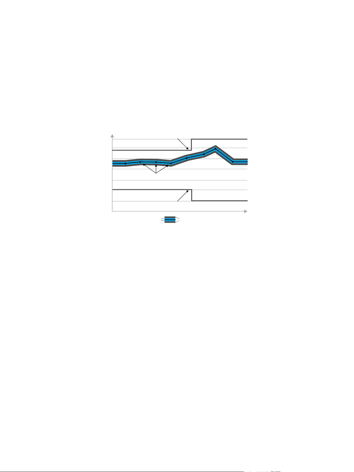
X-axis
Y-axis
Specification limit
Actual values with measurement uncertainty and guard band
Specification limit
Measurement uncertainties Guard band