SMW200A_specs_en_3606-8037-22_v2700.pdf - 第43页
Version 27.00, October 2024 Rohde & Schwar z R&S ® SMW200A Vec tor Signal Generator 43 Digital baseband inputs/outp uts Depending on the installed softwar e and hardwa re options, the R&S ® SMW200A is able to…
Version 27.00, October 2024
42 Rohde & Schwarz R&S
®
SMW200A Vector Signal Generator
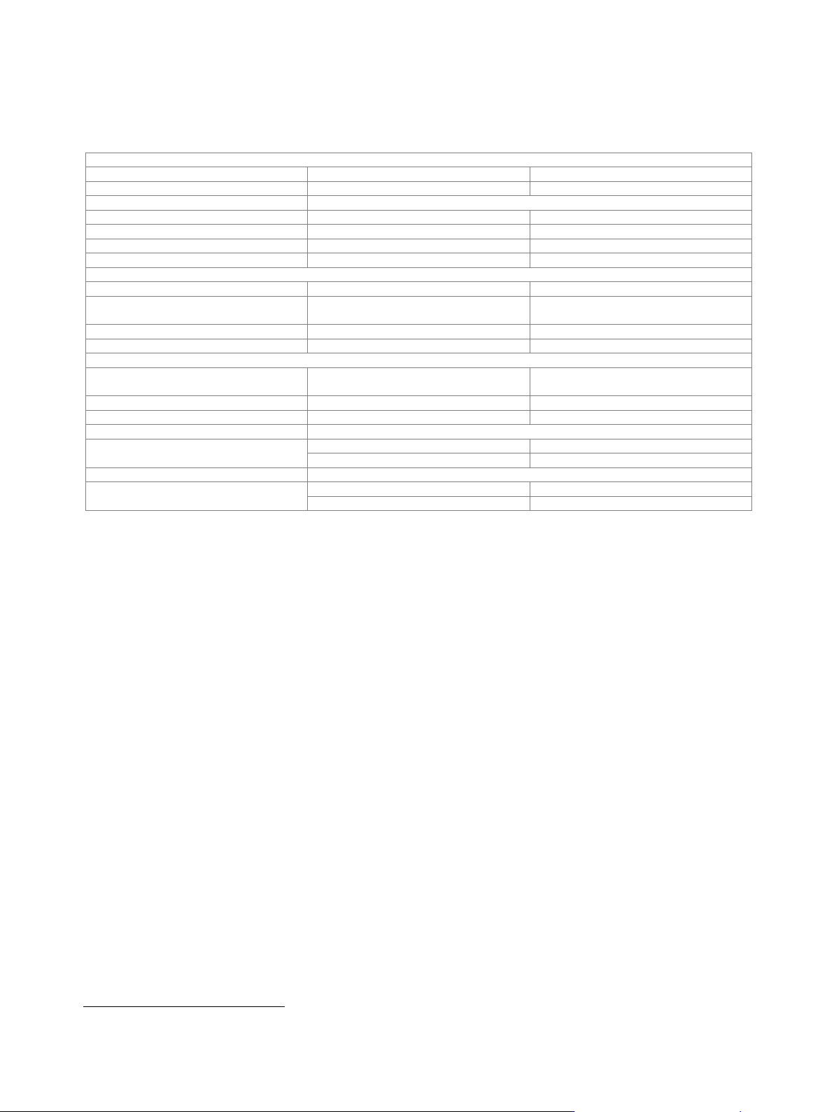
Differential analog I/Q outputs (R&S
®
SMW-K16 option)
This option can be installed once if the instrument is equipped with the R&S
®
SMW-B13 option. If the instrument is equipped with the
R&S
®
SMW-B13T option, differential analog I/Q outputs can be used either on signal path A or B with one R&S
®
SMW-K16 option. For
differential analog I/Q outputs to be used on signal paths A and B simultaneously, two R&S
®
SMW-K16 must be installed.
Output impedance
Single-ended
50 Ω
Differential
100 Ω
Output voltage (V
out
)
output voltage depends on set modulation signal
Single-ended
EMF
0.02 V to 2 V (V
p
)
Resolution
1 mV
Differential
EMF
0.04 V to 4 V (V
pp
)
Resolution
2 mV
Bias voltage (V
bias
)
Single-ended
EMF
–4 V to (+4 V – V
out
)
Differential
EMF
(–4 V + V
out
/ 2 + V
offset
/ 2) to
(+4 V – V
out
/ 2 – V
offset
/ 2)
Resolution
2 mV
Uncertainty
1 % + 4 mV
Offset voltage (V
offset
)
Differential
EMF
(–4 V + V
out
/ 2 + V
bias
/ 2) to
(+4 V – V
out
/ 2 – V
bias
/ 2)
Resolution
0.1 mV
Uncertainty
1 % + 0.1 % · bias voltage + 1 mV
Differential signal balance
at R
L
= 50 Ω, output voltage > 0.5 V (V
p
)
Magnitude
up to 10 MHz
< 0.2 dB, 0.05 dB (meas.)
up to 80 MHz
0.2 dB (meas.)
Frequency response
11
at R
L
= 50 Ω, output voltage > 0.5 V
(V
p
)
Magnitude
up to 10 MHz
0.02 dB (meas.)
up to 80 MHz
0.03 dB (meas.)
11
"Optimize internal I/Q impairments for RF output" switched off.
Version 27.00, October 2024
Rohde & Schwarz R&S
®
SMW200A Vector Signal Generator 43
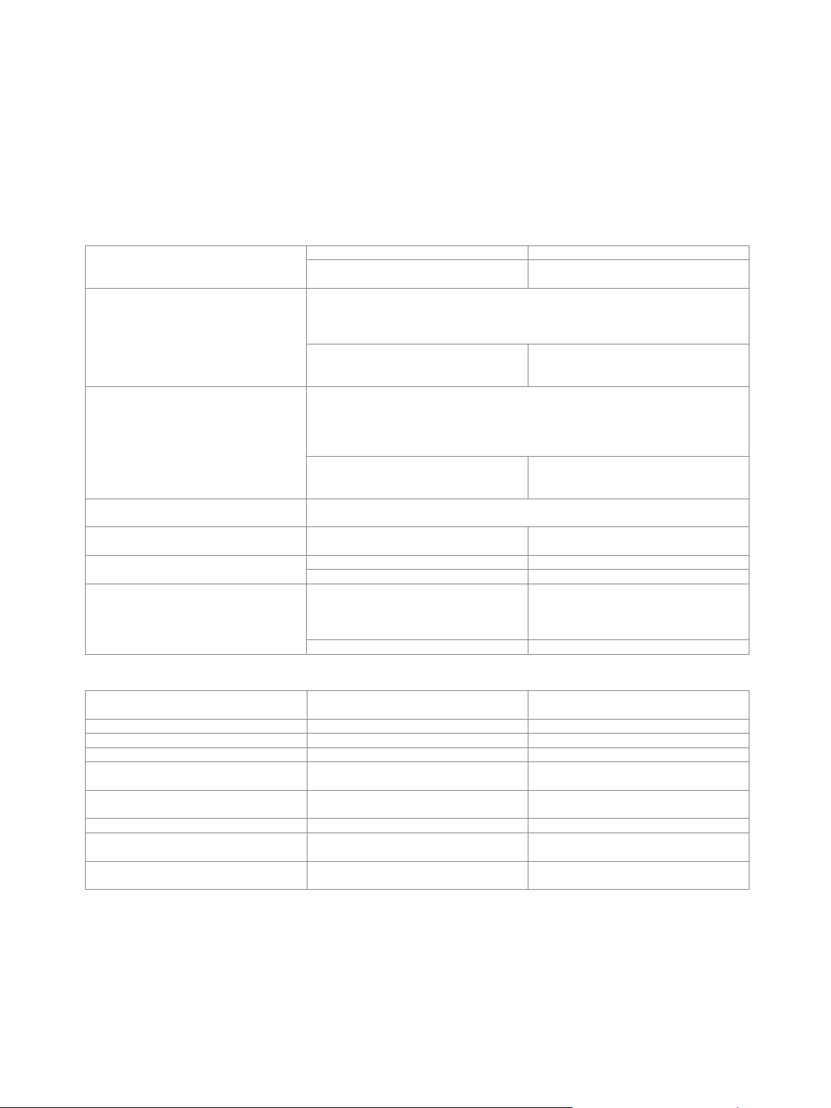
Digital baseband inputs/outputs
Depending on the installed software and hardware options, the R&S
®
SMW200A is able to receive digital baseband signals and to
output digital baseband signals. The digital I/Q input/output can be used for the lossless connection of the R&S
®
SMW200A to the
digital I/Q input/output of other Rohde & Schwarz instruments (for example the CMW500 wideband radio communication tester in
fading applications).
Digital baseband outputs: At least one R&S
®
SMW-K18 option must be installed. This option can be installed once if the instrument is
equipped with the R&S
®
SMW-B13 option. If the instrument is equipped with the R&S
®
SMW-B13T option, digital baseband outputs can
be used either on signal path A or B with one R&S
®
SMW-K18 option. For digital baseband outputs to be used on signal paths A and B
simultaneously, two R&S
®
SMW-K18 must be installed. Furthermore, to enable two or more digital baseband outputs in MIMO modes,
two R&S
®
SMW-K18 must be installed.
Signal outputs
analog and digital, digital only
with 2 × R&S
®
SMW-K18 installed
analog and digital, digital only, digital only
multiplexed
Digital only
The streams are output via the digital I/Q outputs only; analog I/Q outputs are not
available. External modulation signals can be output via the RF outputs (I/Q modulation
mode: external wideband I/Q).
Note: System configurations with more than 4 streams are not available in this mode.
with R&S
®
SMW-K551 installed
The instrument runs at reduced speed
depending on the device connected to the
digital I/Q output (slow I/Q).
Digital only multiplexed
The streams are output via BBMM1 and BBMM2 in multiplexed mode, i.e. up to 4
streams are output via a single digital output. Analog I/Q outputs are not available.
External modulation signals can be output via the RF outputs (I/Q modulation mode:
external wideband I/Q).
Note: All system configurations available on the instrument are available in this mode.
with R&S
®
SMW-K551 installed
The instrument runs at reduced speed
depending on the device connected to the
digital I/Q output (slow I/Q).
Analog and digital
The instrument runs in regular operating mode, both analog and digital outputs are
available, slow I/Q is not possible.
Number of digital outputs
according to selected system configuration
(see table below)
Number of streams per digital output
digital only
1
digital only multiplexed
1 to 4
Bandwidth
general
according to selected system configuration
(see section Multichannel, MIMO, fading
and noise, specifications for
R&S
®
SMW-K74, -K75, -K76 options)
4 streams mapped to one digital output
40 MHz
The following table gives an overview of which software and hardware options are required for which digital I/Q connectivity:
Minimum required R&S
®
SMW200A
options
Digital I/Q inputs
Digital I/Q outputs
R&S
®
SMW-B13 + 1 × R&S
®
SMW-K18
–
1
R&S
®
SMW-B13T + 2 × R&S
®
SMW-K18
–
2
1 × R&S
®
SMW-B10
1
–
1 × R&S
®
SMW-B10 + R&S
®
SMW-B13 +
1 × R&S
®
SMW-K18
1
1
1 × R&S
®
SMW-B10 + R&S
®
SMW-B13T +
2 × R&S
®
SMW-K18
1
2
2 × R&S
®
SMW-B10
2
–
2 × R&S
®
SMW-B10 + R&S
®
SMW-B13 +
1 × R&S
®
SMW-K18
2
1
2 × R&S
®
SMW-B10 + R&S
®
SMW-B13T +
2 × R&S
®
SMW-K18
2
2

Version 27.00, October 2024
44 Rohde & Schwarz R&S
®
SMW200A Vector Signal Generator
2 × R&S
®
SMW-B10 + 4 × R&S
®
SMW-B14
+ R&S
®
SMW-B13T + 2 × R&S
®
SMW-K18
depends on selected system configuration
(for required additional options for specific system configurations, see section
Multichannel, MIMO, fading and noise, specifications for R&S
®
SMW-K74, -K75, -K76
options)
3x1
3
1
3x2
3
2
3x3
3
3
1x3
1
3
2x3
2
3
4x1
4
1
4x2
4
2
4x3
4
3
4x4
4
4
1x4
1
4
2x4
2
4
3x4
3
4
8x1
–
1
8x2
–
2
8x4
–
4
8x8
–
subset 1: 4,
subset 2: 4
1x8
1
6
2x8
2
6
4x8
2
6
3x1x1
3
3
4x1x1
4
4
5x1x1
–
3
6x1x1
–
4
7x1x1
–
5
8x1x1
–
6
2x1x2
2
4
2x2x1
4
2
2x2x2
4
4
2x1x3, 2x2x3
2
5
2x1x4, 2x2x4
2
6
2x3x1, 2x4x1
2
2
2x3x2, 2x4x2
2
4
2x3x3, 2x4x3
–
5
2x3x4, 2x4x4
–
6
3x2x1
2
3
3x1x2, 3x2x2
2
4
4x2x1
2
4
4x1x2, 4x2x2
2
6