SMW200A_specs_en_3606-8037-22_v2700.pdf - 第67页
Version 27.00, October 2024 Rohde & Schwar z R&S ® SMW200A Vec tor Signal Generator 67 Digital Doherty ( R& S ® SMW -K546 optio n) The Digital Dohe rty option only ap plies to instru ments equipped wi th two …

Version 27.00, October 2024
66 Rohde & Schwarz R&S
®
SMW200A Vector Signal Generator
Envelope tracking (R&S
®
SMW-K540 option)
With this option, the analog I/Q outputs can be used to generate an analog signal corresponding to the envelope of the I/Q signal to
test envelope tracking modulators.
This option can be installed once if the instrument is equipped with the R&S
®
SMW-B13 or R&S
®
SMW-B13XT option. If the instrument
is equipped with the R&S
®
SMW-B13T option, envelope tracking can be used either on signal path A or B with one R&S
®
SMW-K540
option. For envelope tracking to be used on signal paths A and B simultaneously, two R&S
®
SMW-K540 and one R&S
®
SMW-B13T
must be installed.
Instruments equipped with the R&S
®
SMW-B13 or R&S
®
SMW-B13T option: For each R&S
®
SMW-K540 option to be installed, an
R&S
®
SMW-K16 option must be installed, and the instrument must be equipped with at least one standard baseband generator
(R&S
®
SMW-B10 option).
Instruments equipped with the R&S
®
SMW-B13XT option: For R&S
®
SMW-K540 option to be installed, the R&S
®
SMW-K17 option must
be installed, and the instrument must be equipped with at least one wideband baseband generator (R&S
®
SMW-B9 option).
General
Envelope voltage adaptation
auto normalized, auto power, manual
Output type
single-ended, differential
Bias voltage
see section Differential analog I/Q outputs or Wideband differential analog I/Q outputs
Offset voltage
see section Differential analog I/Q outputs or Wideband differential analog I/Q outputs
Envelope to RF delay
Setting range
–1 µs to +1 µs
Setting resolution
1 ps
Shaping
off, linear, from table, polynomial,
detroughing
Envelope voltage adaptation modes: auto normalized and auto power
Power amplifier input power P
in
Setting range
–145.00 dB to +30.00 dB
Setting resolution
0.01 dB
Power amplifier supply voltage V
CC
V
CC
= envelope voltage · DC modulator gain + V
CC, Offset
DC modulator gain
–20.00 dB to +20.00 dB
Power amplifier offset voltage V
CC,
Offset
0 V to 30 V
Envelope voltage adaptation mode: manual
Pregain
Setting range
–20.00 dB to 0.00 dB
Setting resolution
0.01 dB
Postgain
Setting range
–3.00 dB to +20.00 dB
Setting resolution
0.01 dB
Clipping level
upper and lower limit can be set
separately
0 % to 100 %
Maximum output voltage
see Output voltage in section Differential analog I/Q outputs
AM/AM, AM/PM predistortion (R&S
®
SMW-K541 option)
Instruments with wideband baseband (R&S
®
SMW-B13XT):
Each R&S
®
SMW-K541 option to be installed requires a wideband baseband generator (R&S
®
SMW-B9 option) and an RF path. If the
instrument is equipped with two baseband generators and two RF paths, predistortion can be used either on signal path A or B with
one R&S
®
SMW-K541 option. To allow AM/AM, AM/PM predistortion to be used on signal paths A and B simultaneously, two
R&S
®
SMW-K541 must be installed; furthermore, the instrument must be equipped with two R&S
®
SMW-B9 options and two RF paths,
i.e. an R&S
®
SMW-B2xx frequency option for path B must be installed.
Instruments with standard baseband (R&S
®
SMW-B13/-B13T):
Each R&S
®
SMW-K541 option to be installed requires a standard baseband generator (R&S
®
SMW-B10 option) and an RF path.
If the instrument is equipped with two baseband generators and two RF paths, predistortion can be used either on signal
path A or B with one R&S
®
SMW-K541 option. To allow AM/AM, AM/PM predistortion to be used on signal paths A and B
simultaneously, two R&S
®
SMW-K541 must be installed; furthermore, the instrument must be equipped with two R&S
®
SMW-B10
options, the R&S
®
SMW-B13T option and two RF paths, i.e. an R&S
®
SMW-B2xx frequency option for path B must be installed.
State
on/off
Maximum input power (PEP
in
max.)
Setting range
–145.00 dB to +30.00 dB
Setting resolution
0.01 dB
Shaping
polynomial, from table
Version 27.00, October 2024
Rohde & Schwarz R&S
®
SMW200A Vector Signal Generator 67
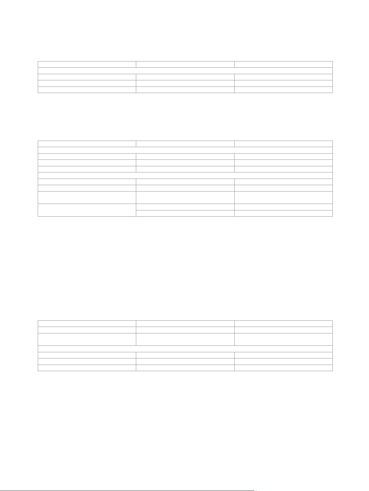
Digital Doherty (R&S
®
SMW-K546 option)
The Digital Doherty option only applies to instruments equipped with two RF paths and two baseband generators. Two
R&S
®
SMW-K541 options and the R&S
®
SMW-B90 option (phase coherence) must be installed as prerequisite.
State
on/off
Maximum input power (PEP
in
max.)
Setting range
–145.00 dB to +30.00 dB
Setting resolution
0.01 dB
Shaping
polynomial, from table, classic Doherty
User-defined frequency response correction (R&S
®
SMW-K544 option)
This option can be installed once if the instrument is equipped with the R&S
®
SMW-B13 option. If the instrument is equipped with the
R&S
®
SMW-B13T or R&S
®
SMW-B13XT option, user-defined frequency response correction can be used either on signal path A or B
with one R&S
®
SMW-K544 option. For user-defined frequency response correction to be used on signal paths A and B simultaneously,
two R&S
®
SMW-K544 must be installed.
State
on/off
Scattering parameters
File format
*.s<n>p (e.g. *.s2p)
Maximum number of points
16384
Number of cascadable datasets
up to 10
Additional frequency response
File format
*.fres, *.ucor
Number of files
up to 5
Absolute level correction at center
frequency
based on S-parameter data
on/off
Minimum compensation bandwidth
with R&S
®
SMW-B13/-B13T options
8 MHz
with R&S
®
SMW-B13XT option
100 MHz
Automated RF port alignment (R&S
®
SMW-K545 option)
Instruments with wideband baseband (R&S
®
SMW-B13XT):
For each installed RF path, R&S
®
SMW-B9, R&S
®
SMW-K61 and R&S
®
SMW-K544 must be installed as prerequisite. Furthermore, the
instrument must be equipped with the R&S
®
SMW-B90 option.
Instruments with standard baseband (R&S
®
SMW-B13/-B13T):
For each installed RF path, R&S
®
SMW-B10, R&S
®
SMW-K61 and R&S
®
SMW-K544 must be installed as prerequisite. Furthermore, the
instrument must be equipped with the R&S
®
SMW-B90 option.
The option cannot be installed if an R&S
®
SMW-B1044O, R&S
®
SMW-B2044O, R&S
®
SMW-B1056O or R&S
®
SMW-B1067O option
is installed.
To run this option a setup should be defined and generated using the R&S
®
RFPAL software. At least two signal paths should be
provided. In case of a setup with multiple instruments, an instrument is designated as primary instrument and should be used to
control the option.
State
on/off
Align
aligned, not aligned
Setup file
setup file including alignment data is
generated by R&S
®
RFPAL
*.rfsa
Additional S-parameter files
File format
*.s<n>p (e.g. *.s2p)
Maximum number of points
16384
Number of cascadable datasets
recommended ≤ 2
up to 10

Version 27.00, October 2024
68 Rohde & Schwarz R&S
®
SMW200A Vector Signal Generator
Crest factor reduction (R&S
®
SMW-K548 option)
Each R&S
®
SMW-K548 option requires a standard baseband generator (R&S
®
SMW-B10 option) or a wideband baseband generator
(R&S
®
SMW-B9 option). If two baseband generators are installed, crest factor reduction can be applied either on path A or B with one
R&S
®
SMW-K548 option. For crest factor reduction to be applied on paths A and B simultaneously, two R&S
®
SMW-K548 must be
installed.
Crest factor reduction can be applied to any waveform loaded in the arbitrary waveform generator.
State
on/off
Algorithm
clipping and filtering
Desired crest factor delta
–20 dB to 0 dB
Maximum iterations
1 to 10
Filter mode “simple”
Signal bandwidth
0 Hz to input file sample rate
Channel spacing
0 Hz to input file sample rate
Filter mode “enhanced”
Passband frequency
0 Hz to ½ of input file sample rate
Stopband frequency
0 Hz to ½ of input file sample rate
Maximum filter order
21 to 300
Slow I/Q (R&S
®
SMW-K551 option)
In slow I/Q mode, the generated signal’s clock rate can be reduced (e.g. a 20 MHz LTE signal is generated with a clock rate of
240 kHz instead of the original 30.72 MHz). This feature can be used to run tests on hardware emulation platforms not yet capable of
full-speed signal processing. The signal and fading characteristics are comparable to those of a system running at full speed. The
actual clock rate of the generated signal is controlled by the device connected to the digital I/Q output connectors of the
R&S
®
SMW200A.
R&S
®
SMW-K551 on instruments with wideband baseband (R&S
®
SMW-B9, R&S
®
SMW-B13XT)
At least one R&S
®
SMW-B9 wideband baseband generator option and one R&S
®
SMW-K19 digital baseband output for wideband
baseband option must be installed.
Note:
Only available for system configuration mode: advanced and signal outputs: digital only (HS).
All digital I/Q outputs need to run at the same clock rate.
The minimum clock rate is limited by the external controlling device only.
The R&S
®
SMW200A can handle varying clock rates.
With activated slow I/Q mode, marker signals are only available via the digital I/Q interface, and not via USER or T/M/C connectors.
With activated slow I/Q mode, no digital baseband inputs are available.
R&S
®
SMW-K551 on instruments with standard baseband (R&S
®
SMW-B10, R&S
®
SMW-B13/-B13T)
At least one R&S
®
SMW-B10 standard baseband generator option and one R&S
®
SMW-K18 digital baseband output option must be
installed.
Note:
All digital I/Q outputs need to run at the same clock rate.
The minimum clock rate is limited by the external controlling device only.
The R&S
®
SMW200A can handle varying clock rates.
In digital only/digital only multiplexed mode, marker signals are only available via the digital I/Q interface, and not via USER or T/M/C
connectors.
In digital only/digital only multiplexed mode with activated slow I/Q, no digital baseband inputs are available.