SMW200A_specs_en_3606-8037-22_v2700.pdf - 第34页
Version 27.00, October 2024 34 Rohde & Schwar z R&S ® SMW200A Vec tor Signal Generator Modulation sources for analog modulation Internal modulation generator Shape s in usoidal Frequency range 0.1 Hz to 1 MHz Res…
Version 27.00, October 2024
Rohde & Schwarz R&S
®
SMW200A Vector Signal Generator 33
Video feedthrough
with R&S
®
SMW-B1003, R&S
®
SMW-B2003, R&S
®
SMW-B1006, R&S
®
SMW-B2006,
R&S
®
SMW-B1007, R&S
®
SMW-B2007 frequency options
level < 10 dBm
< 10 % of RF,
< 200 mV (V
pp
)
with R&S
®
SMW-B1012, R&S
®
SMW-B2012 frequency options
f ≤ 5 GHz: level < 5 dBm
< 10 % of RF,
< 200 mV (V
pp
)
f > 5 GHz: level < 10 dBm
< 10 % of RF,
< 20 mV (V
pp
)
with R&S
®
SMW-B1020, R&S
®
SMW-B2020, R&S
®
SMW-B1031, R&S
®
SMW-B2031,
R&S
®
SMW-B1040, R&S
®
SMW-B1040N, R&S
®
SMW-B1044, R&S
®
SMW-B2044,
R&S
®
SMW-B1044N, R&S
®
SMW-B2044N, R&S
®
SMW-B1044O, R&S
®
SMW-B2044O,
R&S
®
SMW-B1056, R&S
®
SMW-B1056N, R&S
®
SMW-B1056O, R&S
®
SMW-B1067,
R&S
®
SMW-B1067N, R&S
®
SMW-B1067O frequency options
f ≤ 5 GHz: level < 5 dBm
< 10 % of RF,
< 200 mV (V
pp
)
f > 5 GHz: level < 10 dBm or maximum
specified level, whichever is lower
< 10 % of RF,
< 2 mV (V
pp
)
Pulse overshoot
< 10 %
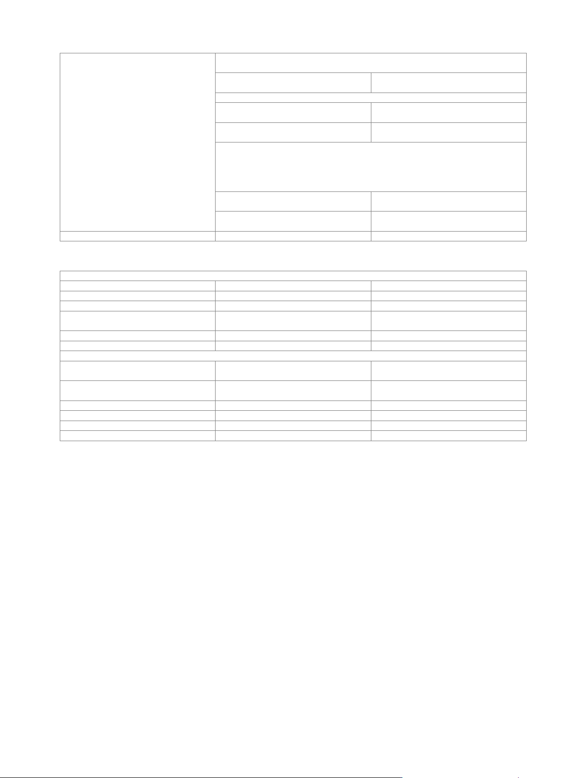
Input for external modulation signals
Modulation inputs EXT 1, EXT 2 for AM/FM/PM
Connector type
EXT 1, EXT 2 on rear panel
BNC female
Input impedance
selectable
100 kΩ or 50 Ω (nom.)
Coupling
AC, DC
Input sensitivity
peak value for set modulation depth or
deviation
1 V (nom.)
Bandwidth
analog input bandwidth
0 Hz to 10 MHz
Input damage voltage
±10 V
Modulation input for pulse modulation
Input
selectable from USER 1, 2, 3 on front
panel or USER 4, 5, 6 on rear panel
Connector type
USER 1, 2, 3 on front panel,
USER 4, 5, 6 on rear panel
BNC female
Input impedance
selectable
1 kΩ or 50 Ω (nom.)
Threshold voltage
0.1 V to 2.0 V (nom.)
Input damage voltage
−0.5 V; 3.8 V
Input polarity
selectable
normal, inverse
Version 27.00, October 2024
34 Rohde & Schwarz R&S
®
SMW200A Vector Signal Generator
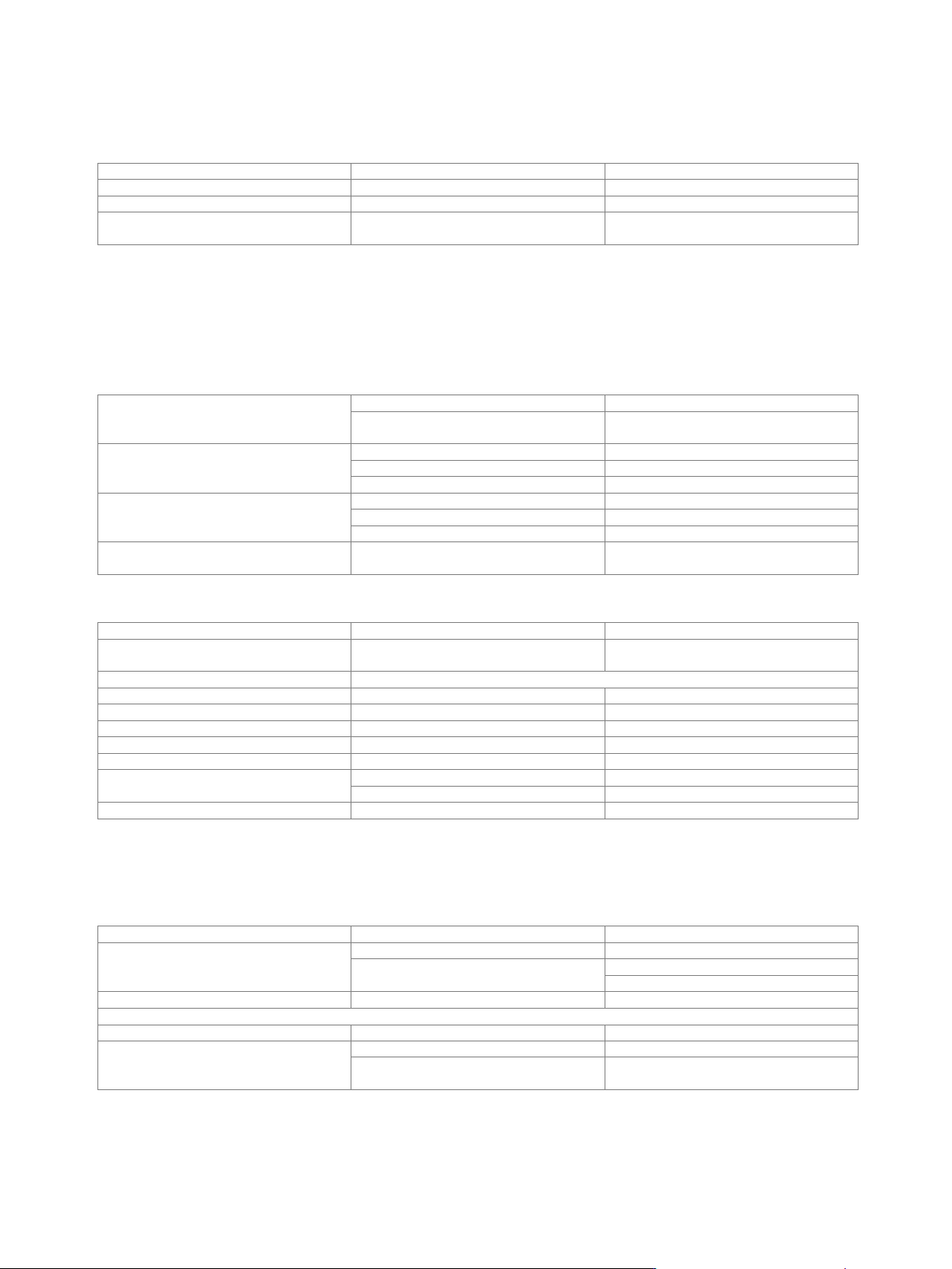
Modulation sources for analog modulation
Internal modulation generator
Shape
sinusoidal
Frequency range
0.1 Hz to 1 MHz
Resolution of setting
0.1 Hz
Frequency uncertainty
< 0.001 Hz + relative deviation of
reference frequency
Multifunction generator (R&S
®
SMW-K24 option)
If two RF paths are installed (signal paths A and B), the multifunction generator can be used either on signal path A or B with one
R&S
®
SMW-K24 option. For the multifunction generator to be used on signal paths A and B simultaneously, two R&S
®
SMW-K24 must
be installed.
The R&S
®
SMW-K24 multifunction generator option consists of three function generators that can be set independently. Two of the
three signal sources can be added with different weighting. The total voltage is limited by the maximum output voltage.
Sources
LF generator 1/2
sine wave, pulse, triangle, trapezoid
noise generator
noise amplitude distribution:
Gaussian, equal
Frequency range
sine wave
0.1 Hz to 10 MHz
pulse, triangle, trapezoid
0.1 Hz to 1 MHz (displayed value)
noise bandwidth
100 kHz to 10 MHz
Resolution of setting
sine wave
0.1 Hz
pulse, triangle, trapezoid
10 ns
noise bandwidth
100 kHz
Frequency uncertainty
< 0.001 Hz + relative deviation of
reference frequency
LF output
Monitoring of resulting modulation signal
for
AM, FM, PM
Source
LF generator 1, LF generator 2, external 1,
external 2, noise generator
Output voltage
V
p
at LF connector, open circuit voltage EMF
Setting range
20 mV to 1 V
Setting resolution
1 mV
Setting accuracy
at 1 kHz
< (1 % of reading + 1 mV)
Output impedance
50 Ω
DC offset
–0.2 V to +2.5 V
Frequency response
sine wave, up to 1 MHz
0.05 dB (meas.)
sine wave, up to 10 MHz
0.1 dB (meas.)
Distortion
f < 100 kHz, at R
L
> 50 Ω, level (V
EMF
) 1 V
< 0.1 %
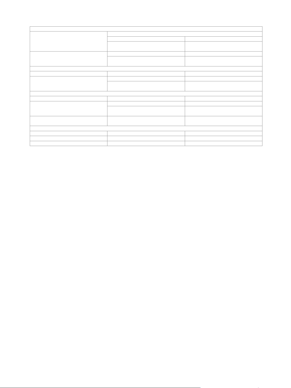
High-performance pulse generator (R&S
®
SMW-K23 option)
If two RF paths are installed (signal paths A and B), the high-performance pulse generator can be used either on signal path A or B
with one R&S
®
SMW-K23 option. For the high-performance pulse generator to be used on signal paths A and B simultaneously, two
R&S
®
SMW-K23 must be installed.
Pulse modes
single pulse, double pulse
Trigger modes
free run, internally triggered
auto
external trigger
external gate
Active trigger edge
positive or negative
Pulse period
Setting range
20 ns to 100 s
Setting resolution
with R&S
®
SMW-B13XT option
3.333 ns
with R&S
®
SMW-B13, R&S
®
SMW-B13T
options
5 ns
Version 27.00, October 2024
Rohde & Schwarz R&S
®
SMW200A Vector Signal Generator 35
Pulse width
Setting range
pulse widths of double pulses are independently settable
with R&S
®
SMW-B13XT option
3.333 ns to 100 s
with R&S
®
SMW-B13, R&S
®
SMW-B13T
options
5 ns to 100 s
Setting resolution
with R&S
®
SMW-B13XT option
3.333 ns
with R&S
®
SMW-B13, R&S
®
SMW-B13T
options
5 ns
Pulse delay
Setting range
0 ns to 100 s
Setting resolution
with R&S
®
SMW-B13XT option
3.333 ns
with R&S
®
SMW-B13, R&S
®
SMW-B13T
options
5 ns
Double-pulse delay
Setting range
20 ns to 1 s
Setting resolution
with R&S
®
SMW-B13XT option
3.333 ns
with R&S
®
SMW-B13, R&S
®
SMW-B13T
options
5 ns
Uncertainty for pulse timing
pulse timing generated digitally; ensured
by design
relative deviation of reference frequency
External trigger
Delay
trigger to RF output
50 ns (meas.)
Jitter
< 10 ns (meas.)
PULSE/VIDEO/SYNC output
LVTTL signal (R
L
≥ 50 Ω)