SMW200A_specs_en_3606-8037-22_v2700.pdf - 第46页
Version 27.00, October 2024 46 Rohde & Schwar z R&S ® SMW200A Vec tor Signal Generator Standard baseband generator (R&S ® SMW-B10 option) – arbitrary waveform mode One or two R&S ® SMW-B10 can b e install…
Version 27.00, October 2024
Rohde & Schwarz R&S
®
SMW200A Vector Signal Generator 45
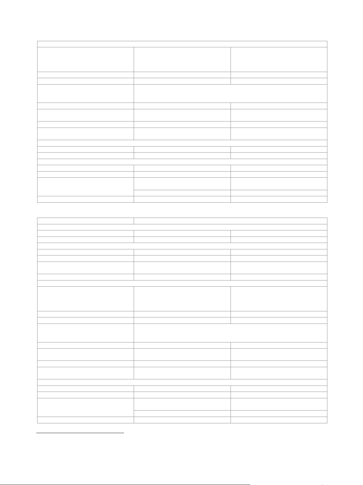
Output parameters
Interface
Standard
in line with R&S
®
Digital I/Q Interface
PAD-R
12
,
I/Q data and control signals, data and
interface clock
Level
LVDS
Connector
26-pin MDR
I/Q sample rate
With source "user-defined", the sample rate must be entered via the parameter "sample
rate", no I/Q data clock being necessary. With source "digital I/Q out", the sample rate
will be estimated on the basis of the applied I/Q data clock.
Source
user-defined, digital I/Q out
Sample rate
maximum sample rate depends on
connected receiving device
400 Hz to 200 MHz
Resolution (user-defined)
0.001 Hz
Frequency uncertainty
(user-defined)
< (5 · 10
−14
+ relative deviation of
reference frequency) · sample rate (nom.)
I/Q data
Resolution
up to 18 bit
Logic format
two’s complement
Physical signal level
Setting range
0 to –60 dBFS
Setting resolution
0.01 dBFS
Bandwidth (RF)
sample rate = 200 MHz
(no interpolation, user-defined)
160 MHz
sample rate < 200 MHz (interpolation)
0.8 · sample rate
Control signals
markers
3
Input parameters
Input level
peak level
Peak level
Setting range
–60 dB to +3 dB, referenced to full scale
Setting resolution
0.01 dB
Crest factor
Setting range
0 dB to +30 dB
Setting resolution
0.01 dB
Adjust level function
automatically determines peak level and
crest factor of input signal
I/Q swap
I and Q signals swapped
on/off
Interface
Standard
in line with R&S
®
Digital I/Q Interface
PAD-R
12
,
I/Q data and control signals, data and
interface clock
Level
LVDS
Connector
26-pin MDR
I/Q sample rate
With source "user-defined", the sample rate must be entered via the parameter "sample
rate", no I/Q data clock being necessary. With source "digital I/Q in", the sample rate
will be estimated on the basis of the applied I/Q data clock.
Source
user-defined, digital I/Q in
Sample rate
maximum sample rate depends on
connected transmitting device
400 Hz to 200 MHz
Resolution (user-defined)
0.001 Hz
Frequency uncertainty
(user-defined)
< (5 · 10
−14
+ relative deviation of
reference frequency) · sample rate (nom.)
I/Q data
Resolution
18 bit
Logic format
two’s complement
Bandwidth (RF)
sample rate = 200 MHz
(no interpolation, user-defined)
160 MHz
sample rate < 200 MHz (interpolation)
0.8 · sample rate
Control signals
markers
3
12
R&S
®
Digital I/Q Interface PAD-R is a Rohde & Schwarz internal company guideline for the transmission of digital I/Q data. It is supported by a wide
range of signal generators, signal analyzers and radio communication testers.
Version 27.00, October 2024
46 Rohde & Schwarz R&S
®
SMW200A Vector Signal Generator
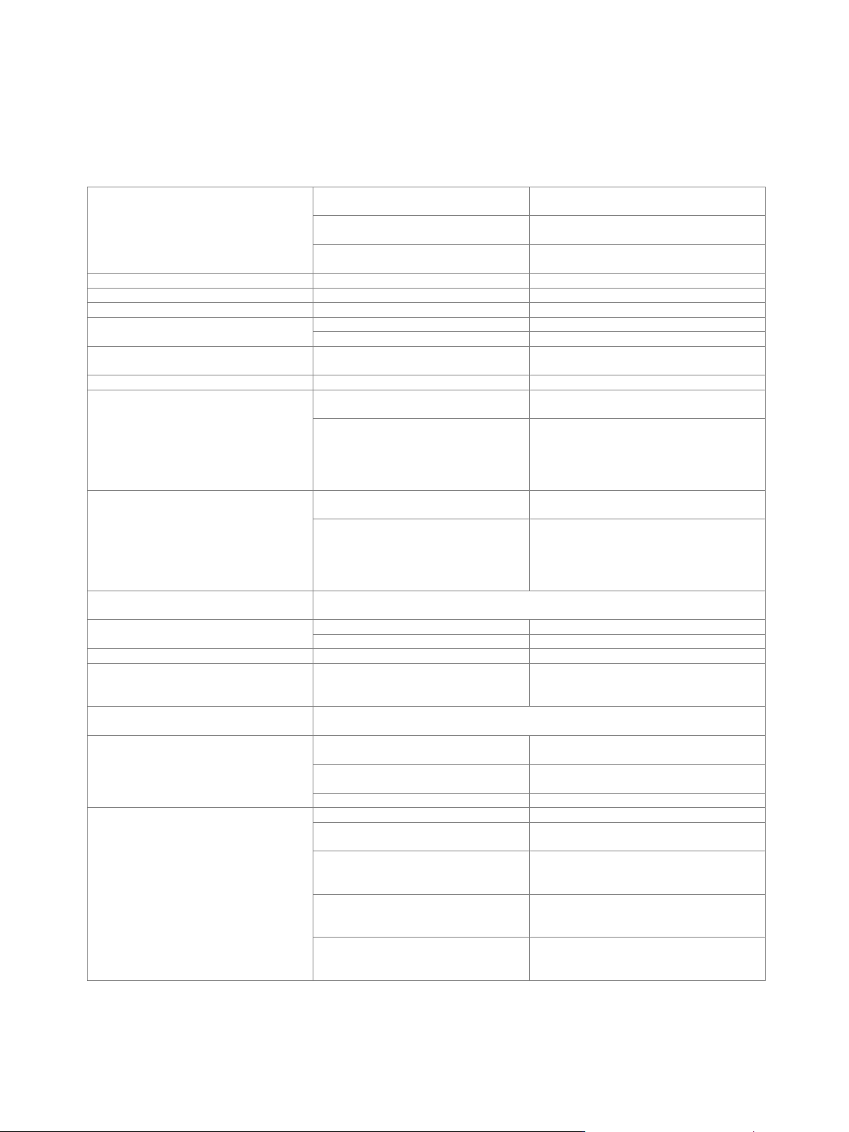
Standard baseband generator (R&S
®
SMW-B10 option) –
arbitrary waveform mode
One or two R&S
®
SMW-B10 can be installed. Their I/Q signals can be assigned a frequency offset and/or be added in the digital
domain with settable level ratio.
Prerequisite: Either R&S
®
SMW-B13 or R&S
®
SMW-B13T must be installed.
Waveform length
1 sample to 64 Msample in one-sample
steps
with R&S
®
SMW-K511 option
(memory extension)
1 sample to 512 Msample in one-sample
steps
with R&S
®
SMW-K512 option
(memory extension)
1 sample to 1 Gsample in one-sample steps
Supported file formats
.wv, .mat, .csv, .iq.tar
Nonvolatile memory
hard disk
Sample resolution
equivalent to D/A converter
16 bit
Sample rate
400 Hz to 150 MHz
with R&S
®
SMW-K522 option
400 Hz to 200 MHz
Sample frequency error
internal clock
< (5 · 10
−14
+ relative deviation of reference
frequency) · sample rate (nom.)
Sample clock source
internal, external
Bandwidth (RF)
using the maximum sample rate,
rolloff to –0.1 dB
120 MHz
using a reduced sample rate,
rolloff to –0.1 dB
(The waveform is automatically
interpolated to the internal sample rate
of 150 MHz.)
0.8 · sample rate
Bandwidth (RF) with R&S
®
SMW-K522
option
using the maximum sample rate,
rolloff to –0.1 dB
160 MHz
using a reduced sample rate,
rolloff to –0.1 dB
(The waveform is automatically
interpolated to the internal sample rate
of 200 MHz.)
0.8 · sample rate
Frequency offset
The frequency offset can be used to shift the center frequency of the wanted baseband
signal. The restrictions caused by the modulation bandwidth still apply.
Frequency offset setting range
–60 MHz to +60 MHz
with R&S
®
SMW-K522 option
–80 MHz to +80 MHz
Frequency offset setting resolution
0.01 Hz
Frequency offset error
< 7 · 10
–7
Hz + relative deviation of
reference frequency · frequency offset
(nom.)
Triggering
A trigger event restarts I/Q generation. The I/Q signal is then synchronous with the
trigger (with a specific timing jitter).
Trigger source
event triggered via GUI or remote
command
internal
event triggered by other baseband
generator
internal (baseband A/B)
event triggered by external trigger signal
external
Trigger modes
The signal is generated continuously.
auto
The signal is generated continuously.
A trigger event causes a restart.
retrig
The signal is started only when a trigger
event occurs. Subsequent trigger
events are ignored.
armed auto
The signal is started only when a trigger
event occurs. Every subsequent trigger
event causes a restart.
armed retrig
The signal is started only when a trigger
event occurs. The signal is generated
once.
single
Version 27.00, October 2024
Rohde & Schwarz R&S
®
SMW200A Vector Signal Generator 47
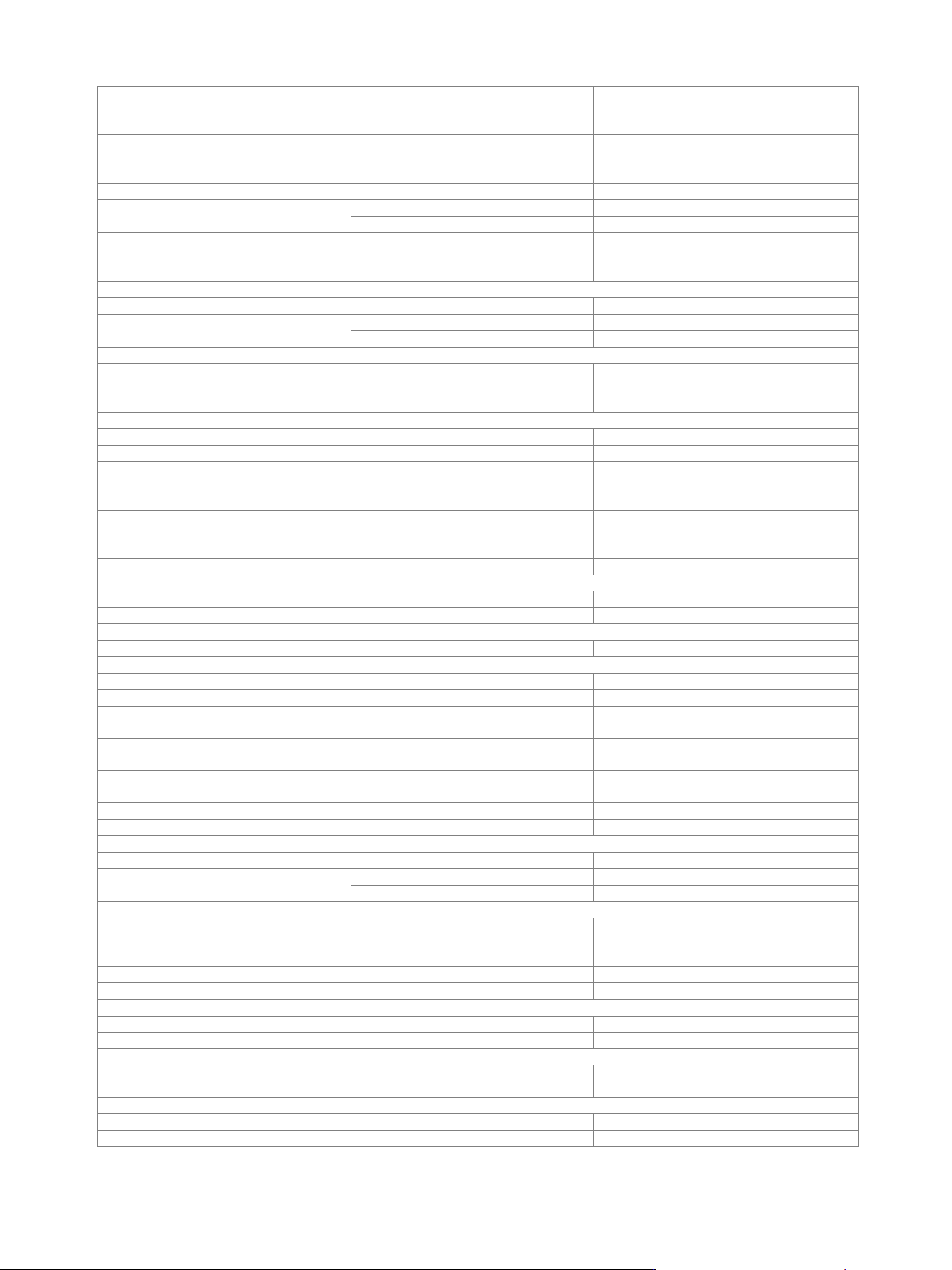
External trigger input
selectable from USER 1, 2, 3 on front panel
or T/M/C 1, T/M 2, T/M 3 of respective
baseband generator on rear panel
Connector type
USER 1, 2, 3 on front panel,
T/M/C 1, T/M 2, T/M 3 of respective
baseband generator on rear panel
BNC female
Input level
0 V to 3 V (nom.)
Threshold
USER 1, 2, 3
settable from 0.1 V to 2.0 V
T/M/C 1, T/M 2, T/M 3
settable from 0.3 V to 2.0 V
Input damage voltage
–0.5 V; 3.8 V
Input impedance
selectable
1 kΩ or 50 Ω (nom.)
Trigger jitter
±2.5 ns
External trigger delay
Setting range
0 sample to 2.147 · 10
9
sample
Setting resolution
without R&S
®
SMW-B14 option
5 ns
with R&S
®
SMW-B14 option
1/fading clock rate (= 5 ns or 10 ns)
External trigger inhibit
Setting range
0 sample to (21.47 s · sample rate) sample
Setting resolution
1 sample
External trigger pulse width
> 7.5 ns
Marker signals
Number of marker signals
3
Operating modes
unchanged, restart, pulse, pattern, ratio
Marker outputs
selectable from USER 1, 2, 3 on front panel
or T/M/C 1, T/M 2, T/M 3 of respective
baseband generator on rear panel
Connector type
USER 1, 2, 3 on front panel,
T/M/C 1, T/M 2, T/M 3 of respective
baseband generator on rear panel
BNC female
Level
LVTTL
Marker delay
Setting range
0 sample to (waveform length – 1) sample
Setting resolution
1 sample
Marker duration
Minimum value
1 sample
Multisegment waveform mode
Number of segments
1 to 1024
Changeover modes
GUI, remote control, external trigger
Extended trigger modes
same segment, next segment, next
segment seamless, sequencer
Changeover time
at 50 MHz clock rate, external trigger,
without clock change
20 µs (meas.)
Seamless changeover
output up to end of current segment,
followed by changeover to next segment
Sequencer play list length
max. 1024
Sequencer segment repetitions
max. 1 048 575
Multicarrier waveform mode
Number of carriers
max. 512
Total RF bandwidth
max. 120 MHz
with R&S
®
SMW-K522 option
max. 160 MHz
Carrier spacing
Setting range
depends on number of carriers and signal
RF bandwidth
Setting resolution
0.01 Hz
Crest factor modes
maximize, minimize, off
Signal period modes
longest file, shortest file, user (max. 1 s)
Single carrier gain
Setting range
–80 dB to 0 dB
Setting resolution
0.01 dB
Single carrier start phase
Setting range
0° to 360°
Setting resolution
0.01°
Single carrier delay
Setting range
0 s to 1 s
Setting resolution
1 ns