SMW200A_specs_en_3606-8037-22_v2700.pdf - 第49页
Version 27.00, October 2024 Rohde & Schwar z R&S ® SMW200A Vec tor Signal Generator 49 Standard baseband generator (R&S ® SMW-B10 option) – real -time operation (custom digital modulation) See Digital Standar…

Version 27.00, October 2024
48 Rohde & Schwarz R&S
®
SMW200A Vector Signal Generator
Extended sequencing (R&S
®
SMW-K501 option)
The R&S
®
SMW-K501 option enables waveform sequencing and real-time signal generation for ultra long playtime. Waveform
variations such as offset frequency, amplitude and phase are calculated in real-time and do not require precalculated waveforms.
The R&S
®
SMW-K501 option offers two different modes:
In user mode, all sequences are based on user-defined XML based lists with up to 5 levels of nested loops. Special list types for
frequency changes over time and amplitude changes over time are also available.
In pulse sequencer mode, the extended sequencing is controlled by the external R&S
®
Pulse Sequencer Software, a powerful software
tool for simulating complex sequencing scenarios.
At least one R&S
®
SMW-B10 option (standard baseband generator) must be installed. If two R&S
®
SMW-B10 options are installed
(signal paths A and B), extended sequencing can be used either on signal path A or B with one R&S
®
SMW-K501 option. For extended
sequencing to be used simultaneously on signal paths A and B, two R&S
®
SMW-K501 options must be installed.
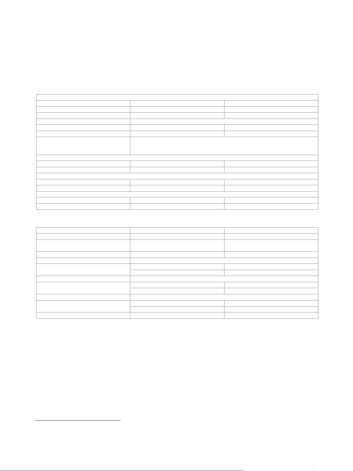
General settings
Modes
sequencing via user-defined XML lists
user
controlled by external
R&S
®
Pulse Sequencer Software
(R&S
®
SMW-K300 required)
pulse sequencer
User mode
List types
Sequencing lists define an arbitrary
number of entries that represent either a
waveform or a sublist with further entries.
sequencing list
Time lists store a list of different off times
between waveform segments. They can
be referenced in sequence entries.
time list
Attenuation lists define the power level of
the output signal over time.
attenuation list
Hopping lists define frequency offsets of
the output signal over time.
hopping list
Sequence
link to a sequencing list XML file
Attenuation over time
link to an attenuation list XML file
Hopping
link to a hopping list XML file
Pulse sequencer mode
see R&S
®
Pulse Sequencer Software specifications (PD 3607.1388.22)
Waveform segments
Segment length
1 sample to 64 Msample
Minimum memory allocation
64 sample
Maximum number of segments
depends on segment lengths and
baseband generator ARB memory size
Waveform sequences
Sequencing
continuously repeating
Maximum number of segments per
sequence
depends on segment lengths and
baseband generator ARB memory size
Maximum number of segment repetitions
2
32
Clock
see section Standard baseband generator
(R&S
®
SMW-B10 option) – arbitrary
waveform mode
Triggering
see section Standard baseband generator
(R&S
®
SMW-B10 option) – arbitrary
waveform mode
Marker signals
Number of marker signals
3
Operating modes
marker at every start of sequence
restart
marker 1 embedded in waveform
unchanged
XML-defined marker for each entry
entry
Marker outputs
see section Standard baseband generator
(R&S
®
SMW-B10 option) – arbitrary
waveform mode
Marker delay
see section Standard baseband generator
(R&S
®
SMW-B10 option) – arbitrary
waveform mode
Marker duration
see section Standard baseband generator
(R&S
®
SMW-B10 option) – arbitrary
waveform mode

Version 27.00, October 2024
Rohde & Schwarz R&S
®
SMW200A Vector Signal Generator 49
Standard baseband generator (R&S
®
SMW-B10 option) –
real-time operation (custom digital modulation)
See Digital Standards for Signal Generators specifications (PD 5213.9434.22).
Version 27.00, October 2024
50 Rohde & Schwarz R&S
®
SMW200A Vector Signal Generator
Wideband baseband characteristics
Internal baseband characteristics (R&S
®
SMW-B13XT option)
The R&S
®
SMW-B13XT provides I/Q paths that can be routed to the installed RF paths or to the analog I/Q outputs. Up to two signals
can be output at the same time, for example:
• Signal A is routed to RF path A, signal B to RF path B
• Signal A is routed to RF path A, signal B to analog I/Q out 1
D/A converter
Data rate
2400 MHz
Resolution
14 bit
Sample rate
4800 MHz (internal interpolation · 2)
Aliasing filter
with amplitude, group delay and S
i
correction
Bandwidth, rolloff to –0.1 dB
1000 MHz
SFDR overall
> 55 dB
I/Q impairments (digital baseband)
These impairments are set in the digital baseband section of the R&S
®
SMW200A. They
act on the I/Q signal sent to the I/Q modulator/RF section, as well as on the I/Q signals
at the analog or digital I/Q outputs (of the respective path).
Carrier leakage
Setting range
–10 % to +10 %
Setting resolution
0.01 %
I Q (imbalance)
Setting range
–1 dB to +1 dB
Setting resolution
0.01 dB
Quadrature offset
Setting range
–10° to +10°
Setting resolution
0.01°
Wideband analog I/Q outputs (R&S
®
SMW-B13XT option)
Number of I/Q outputs
single-ended
2
Output impedance
50 Ω
Output voltage
EMF (output voltage depends on set
modulation signal)
1 V (V
p
)
Offset
EMF
< 1 mV
Frequency response
13
at R
L
= 50 Ω
Magnitude
up to 100 MHz
0.1 dB (meas.)
up to 1000 MHz
0.2 dB (meas.)
I/Q balance
14
at R
L
= 50 Ω
Magnitude
up to 100 MHz
0.1 dB (meas.)
up to 1000 MHz
0.1 dB (meas.)
Spectral purity
at R
L
= 50 Ω
SFDR (sine wave)
100 MHz
> 60 dB
up to 1000 MHz
55 dB (meas.)
Wideband noise
10 MHz sine wave at 1 MHz offset
–155 dBc (typ.)
13
"Optimize internal I/Q impairments for RF output" switched off.
14
Value applies after 1 hour warm-up time and recalibration for 4 hours of operation and temperature variations of less than +5 °C.