SMW200A_specs_en_3606-8037-22_v2700.pdf - 第65页
Version 27.00, October 2024 Rohde & Schwar z R&S ® SMW200A Vec tor Signal Generator 65 Impulsive noise simulatio n This function allow s to add a pul sed AWGN signal to the wanted signal with se ttable number of …
Version 27.00, October 2024
64 Rohde & Schwarz R&S
®
SMW200A Vector Signal Generator
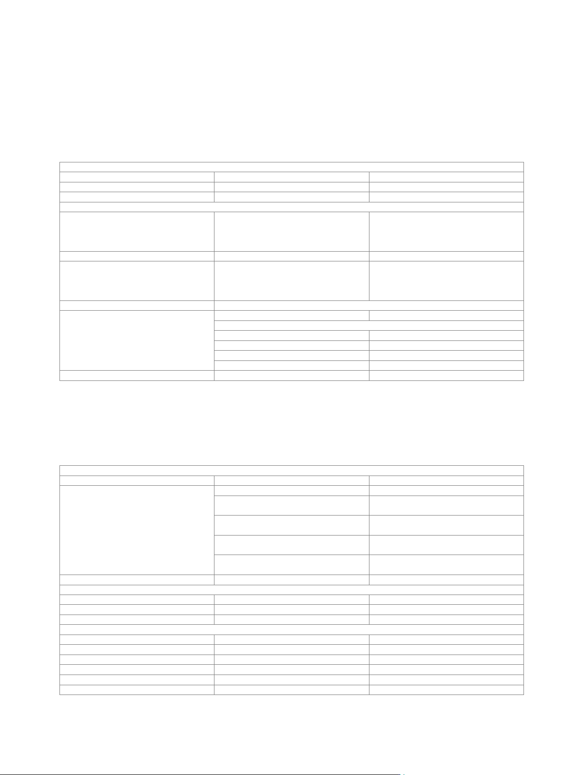
Baseband enhancements
Additive white Gaussian noise (AWGN) (R&S
®
SMW-K62 option)
AWGN can be generated either on path A or B with one R&S
®
SMW-K62 option. For AWGN to be generated on paths A and B
simultaneously, two R&S
®
SMW-K62 must be installed, and the R&S
®
SMW200A must be equipped with the R&S
®
SMW-B13T or
R&S
®
SMW-B13XT option.
Addition of an AWGN signal of settable bandwidth and settable C/N ratio or E
b
/N
0
to a wanted signal. If the noise generator is used,
a frequency offset cannot be added to the wanted signal.
Noise
Distribution density
Gaussian, statistical, separate for I and Q
Crest factor
> 15 dB
Periodicity
> 3 · 10
10
s
C/N, E
b
/N
0
Setting range
Depends on the set RF level.
The PEP of the sum signal (wanted signal
+ noise) must not exceed the maximum
possible PEP of the respective RF path.
–50 dB to +45 dB
Setting resolution
0.01 dB
Uncertainty
for system bandwidth = symbol rate,
symbol rate < 4 MHz,
–24 dB < C/N < 30 dB and
crest factor < 12 dB
< 0.1 dB
System bandwidth
bandwidth for determining noise power
Setting range
with R&S
®
SMW-B13/-B13T options
1 kHz to 160 MHz
with R&S
®
SMW-B13XT option
system configuration mode: standard
1 kHz to 2000 MHz
system configuration mode: advanced
1 kHz to 200 MHz
with R&S
®
SMW-K822 option
1 kHz to 400 MHz
with R&S
®
SMW-K823 option
1 kHz to 800 MHz
Setting resolution
100 Hz
Enhanced noise generation (R&S
®
SMW-K810 option)
Enhanced noise generation can be used either on signal path A or B with one R&S
®
SMW-K810 option. For enhanced noise
generation to be used on paths A and B simultaneously, two R&S
®
SMW-K810 must be installed. For each R&S
®
SMW-K810 option to
be installed, an R&S
®
SMW-K62 option must be installed as prerequisite.
Phase noise simulation
Phase noise
Injection
after fading
Profiles
user-defined
user
predefined PLL phase noise profiles
(simulation of typical PLL circuits)
PLL 1, PLL 2
predefined VCXO phase noise profiles
(simulation of typical oscillator circuits)
crystal 1 to 5
predefined DVB-S2 phase noise profiles,
based on EN 302307, DIRECTV
DVB-S2 P1, DVB-S2 P2, DVB-S2 D1,
DVB-S2 A1, DVB-S2 A2
predefined ATSC phase noise profiles,
based on ATSC A.74
ATSC A.74
File format
text files, editable
Graphical user interface
Entry
by curve table
Number of nodes
5 independent points
Calculation
internal
Amplitude at f
carrier
± 100 Hz
Setting range
measurement bandwidth = 1 Hz
–110.00 dBc to 0.00 dBc
Setting resolution
measurement bandwidth = 1 Hz
0.01 dB
Maximum phase angle
±180°
Density distribution function
Gaussian
Frequency response
depends on phase noise profile
System bandwidth
10 MHz
Version 27.00, October 2024
Rohde & Schwarz R&S
®
SMW200A Vector Signal Generator 65
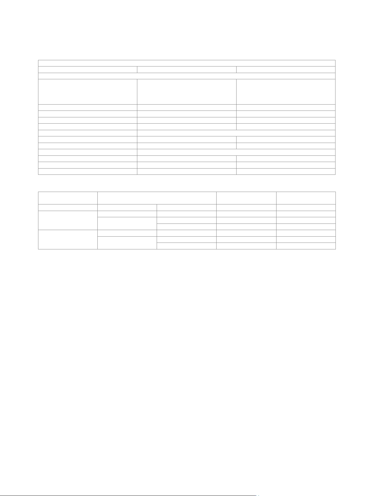
Impulsive noise simulation
This function allows to add a pulsed AWGN signal to the wanted signal with settable number of pulses per frame and within settable
limits of randomly distributed pulse intervals.
Impulsive noise
AWGN signal data
see R&S
®
SMW-K62 option
C/I
Setting range
Depends on the set RF level.
The PEP of the sum signal (wanted signal
+ noise) must not exceed the maximum
possible PEP of the respective RF path.
–35 dB to +60 dB
Setting resolution
0.01 dB
Frame duration
0.1 ms to 1000.0 ms
Pulse duration
fixed
0.25 µs
Pulses per frame
1 to 40000
Minimum pulse interval
for pulses per frame > 1
Setting range
0.25 µs to 16 ms
Setting resolution
0.25 µs
Maximum pulse interval
for pulses per frame > 1
Setting range
0.25 µs to 16 ms
Setting resolution
0.25 µs
Distribution of pulse intervals
PRBS
Availability of phase noise and impulsive noise for different baseband configurations
Baseband main
module
Fading/baseband configuration
Phase noise
Impulsive noise
R&S
®
SMW-B13
standard
●
●
R&S
®
SMW-B13T
standard
●
●
advanced
up to 4 streams
–
●
more than 4 streams
–
–
R&S
®
SMW-B13XT
standard
●
●
advanced
up to 4 streams
●
●
more than 4 streams
●
●

Version 27.00, October 2024
66 Rohde & Schwarz R&S
®
SMW200A Vector Signal Generator
Envelope tracking (R&S
®
SMW-K540 option)
With this option, the analog I/Q outputs can be used to generate an analog signal corresponding to the envelope of the I/Q signal to
test envelope tracking modulators.
This option can be installed once if the instrument is equipped with the R&S
®
SMW-B13 or R&S
®
SMW-B13XT option. If the instrument
is equipped with the R&S
®
SMW-B13T option, envelope tracking can be used either on signal path A or B with one R&S
®
SMW-K540
option. For envelope tracking to be used on signal paths A and B simultaneously, two R&S
®
SMW-K540 and one R&S
®
SMW-B13T
must be installed.
Instruments equipped with the R&S
®
SMW-B13 or R&S
®
SMW-B13T option: For each R&S
®
SMW-K540 option to be installed, an
R&S
®
SMW-K16 option must be installed, and the instrument must be equipped with at least one standard baseband generator
(R&S
®
SMW-B10 option).
Instruments equipped with the R&S
®
SMW-B13XT option: For R&S
®
SMW-K540 option to be installed, the R&S
®
SMW-K17 option must
be installed, and the instrument must be equipped with at least one wideband baseband generator (R&S
®
SMW-B9 option).
General
Envelope voltage adaptation
auto normalized, auto power, manual
Output type
single-ended, differential
Bias voltage
see section Differential analog I/Q outputs or Wideband differential analog I/Q outputs
Offset voltage
see section Differential analog I/Q outputs or Wideband differential analog I/Q outputs
Envelope to RF delay
Setting range
–1 µs to +1 µs
Setting resolution
1 ps
Shaping
off, linear, from table, polynomial,
detroughing
Envelope voltage adaptation modes: auto normalized and auto power
Power amplifier input power P
in
Setting range
–145.00 dB to +30.00 dB
Setting resolution
0.01 dB
Power amplifier supply voltage V
CC
V
CC
= envelope voltage · DC modulator gain + V
CC, Offset
DC modulator gain
–20.00 dB to +20.00 dB
Power amplifier offset voltage V
CC,
Offset
0 V to 30 V
Envelope voltage adaptation mode: manual
Pregain
Setting range
–20.00 dB to 0.00 dB
Setting resolution
0.01 dB
Postgain
Setting range
–3.00 dB to +20.00 dB
Setting resolution
0.01 dB
Clipping level
upper and lower limit can be set
separately
0 % to 100 %
Maximum output voltage
see Output voltage in section Differential analog I/Q outputs
AM/AM, AM/PM predistortion (R&S
®
SMW-K541 option)
Instruments with wideband baseband (R&S
®
SMW-B13XT):
Each R&S
®
SMW-K541 option to be installed requires a wideband baseband generator (R&S
®
SMW-B9 option) and an RF path. If the
instrument is equipped with two baseband generators and two RF paths, predistortion can be used either on signal path A or B with
one R&S
®
SMW-K541 option. To allow AM/AM, AM/PM predistortion to be used on signal paths A and B simultaneously, two
R&S
®
SMW-K541 must be installed; furthermore, the instrument must be equipped with two R&S
®
SMW-B9 options and two RF paths,
i.e. an R&S
®
SMW-B2xx frequency option for path B must be installed.
Instruments with standard baseband (R&S
®
SMW-B13/-B13T):
Each R&S
®
SMW-K541 option to be installed requires a standard baseband generator (R&S
®
SMW-B10 option) and an RF path.
If the instrument is equipped with two baseband generators and two RF paths, predistortion can be used either on signal
path A or B with one R&S
®
SMW-K541 option. To allow AM/AM, AM/PM predistortion to be used on signal paths A and B
simultaneously, two R&S
®
SMW-K541 must be installed; furthermore, the instrument must be equipped with two R&S
®
SMW-B10
options, the R&S
®
SMW-B13T option and two RF paths, i.e. an R&S
®
SMW-B2xx frequency option for path B must be installed.
State
on/off
Maximum input power (PEP
in
max.)
Setting range
–145.00 dB to +30.00 dB
Setting resolution
0.01 dB
Shaping
polynomial, from table