SMW200A_specs_en_3606-8037-22_v2700.pdf - 第29页
Version 27.00, October 2024 Rohde & Schwar z R&S ® SMW200A Vec tor Signal Generator 29 Simultaneous modulation In the same RF path. ● = compatible, – = incompatible ○ = compatible w ith limitations (AL C mode = o…
Version 27.00, October 2024
28 Rohde & Schwarz R&S
®
SMW200A Vector Signal Generator
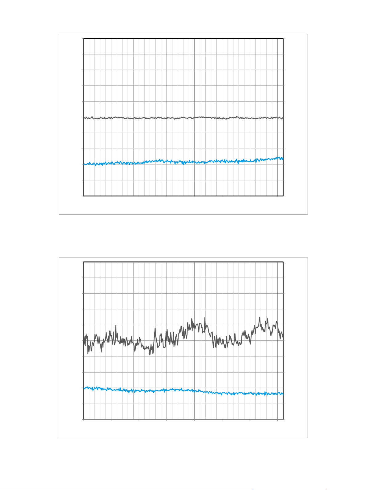
Measured relative phase between two LO coupled R&S
®
SMW200A RF paths versus time, carrier frequency = 2 GHz, level = –10 dBm
(the lower curve/right vertical axis indicates the temperature variation)
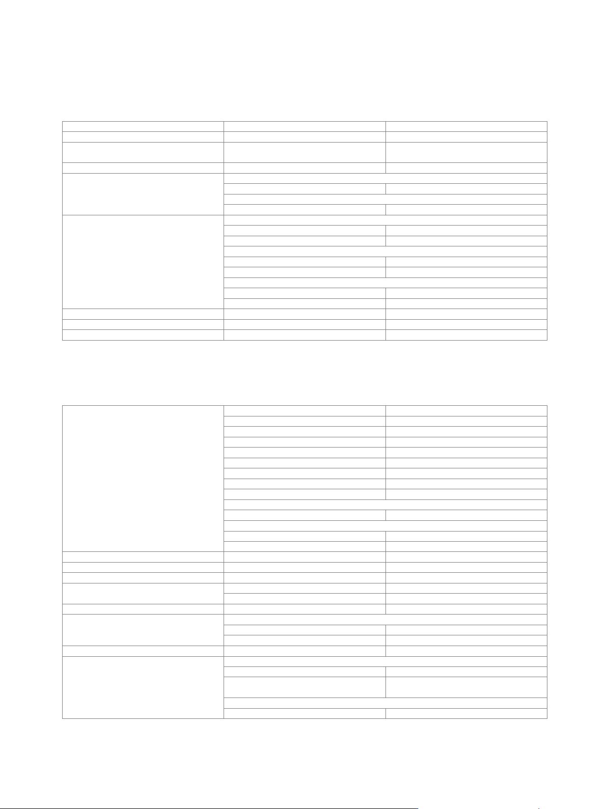
Measured relative phase between two LO coupled R&S
®
SMW200A RF paths versus time, carrier frequency = 40 GHz, level = –10 dBm
(the lower curve/right vertical axis indicates the temperature variation)
-0.20
-0.10
0.00
0.10
0.20
0.30
0.40
0.50
0.60
0.70
0.80
-1.00
-0.80
-0.60
-0.40
-0.20
0.00
0.20
0.40
0.60
0.80
1.00
0 500 1000 1500 2000 2500 3000 3500
Relative temperature /
°C
Relative phase /
°
Time / s
-0.20
-0.10
0.00
0.10
0.20
0.30
0.40
0.50
0.60
0.70
0.80
-1.00
-0.80
-0.60
-0.40
-0.20
0.00
0.20
0.40
0.60
0.80
1.00
0 500 1000 1500 2000 2500 3000 3500
Relative temperature /
°C
Relative phase /
°
Time / s

Version 27.00, October 2024
Rohde & Schwarz R&S
®
SMW200A Vector Signal Generator 29
Simultaneous modulation
In the same RF path.
● = compatible, – = incompatible
○ = compatible with limitations (ALC mode = off)
Amplitude
modulation
Frequency
modulation
Phase modulation
Pulse modulation
I/Q modulation
Amplitude
modulation
●
●
○
–
Frequency
modulation
●
–
●
●
Phase modulation
●
–
●
●
Pulse modulation
○
●
●
○
I/Q modulation
–
●
●
○
Two-path instruments: Frequency modulation and phase modulation are not compatible with I/Q modulation in the other RF path.
For simultaneous I/Q and frequency modulation, or simultaneous I/Q and phase modulation, the instrument must be equipped with a
two-path signal routing and baseband main module (R&S
®
SMW-B13T or R&S
®
SMW-B13XT option).
Instruments equipped with R&S
®
SMW-B2031, R&S
®
SMW-B2044, R&S
®
SMW-B2044N or R&S
®
SMW-B2044O in RF path B:
Amplitude modulation, frequency modulation and phase modulation are only possible in RF path A. When activating frequency or
phase modulation in RF path A, RF path B is switched off.
Version 27.00, October 2024
30 Rohde & Schwarz R&S
®
SMW200A Vector Signal Generator
Analog modulation
Amplitude modulation (R&S
®
SMW-K720 option)
This option is not available for R&S
®
SMW-B2031, R&S
®
SMW-B2044, R&S
®
SMW-B2044N and R&S
®
SMW-B2044O.
Modulation source
internal, external
External coupling
AC, DC
Modulation depth
modulation is clipped at high levels when
maximum PEP is reached
0 % to 100 %
Resolution of setting
0.1 %
AM depth (m) error
f ≤ 20 GHz
f
mod
= 1 kHz and m < 80 %
< (1 % of reading + 1 %)
20 GHz < f
f
mod
= 1 kHz and m < 80 %
< (2 % of reading + 1 %)
AM distortion
f ≤ 3 GHz, f
mod
= 1 kHz
m = 30 %
< 0.8 %
m = 80 %
< 1.4 %
3 GHz < f ≤ 20 GHz, f
mod
= 1 kHz
m = 30 %
< 1 %
m = 80 %
< 1.6 %
20 GHz < f, f
mod
= 1 kHz, level = 0 dBm
m = 30 %
< 1.5 %
m = 80 %
< 2.4 %
Modulation frequency range
DC, 20 Hz to 500 kHz
Modulation frequency response
AC mode, 20 Hz to 500 kHz
< 1 dB
Incidental PM at AM
m = 30 %, f
mod
= 1 kHz, peak value
< 0.1 rad
Frequency modulation (R&S
®
SMW-K720 option)
R&S
®
SMW-B13T or R&S
®
SMW-B13XT must be installed.
This option is not available for R&S
®
SMW-B2031, R&S
®
SMW-B2044, R&S
®
SMW-B2044N and R&S
®
SMW-B2044O.
FM multiplier (N) for different frequency
ranges
100 kHz ≤ f ≤ 200 MHz
N = 1
200 MHz < f ≤ 375 MHz
N = 1/4
375 MHz < f ≤ 750 MHz
N = 1/2
750 MHz < f ≤ 1500 MHz
N = 1
1.5 GHz < f ≤ 3 GHz
N = 2
3 GHz < f ≤ 6 GHz
N = 4
6 GHz < f ≤ 12 GHz
N = 8
12 GHz < f ≤ 24 GHz
N = 16
24 GHz < f ≤ 44 GHz
N = 32
R&S
®
SMW-B1056, R&S
®
SMW-B1056N, R&S
®
SMW-B1056O
43 GHz < f ≤ 56 GHz
N = 40
R&S
®
SMW-B1067, R&S
®
SMW-B1067N, R&S
®
SMW-B1067O
43 GHz < f ≤ 60 GHz
N = 40
60 GHz < f ≤ 67 GHz
N = 80
Modulation source
internal, external, internal and external
External coupling
AC, DC
FM modes
normal, low noise
Maximum deviation
FM mode: normal
N · 10 MHz
FM mode: low noise
N · 100 kHz
Resolution of setting
< 200 ppm, min. N · 0.1 Hz
FM deviation error
f
mod
= 10 kHz, deviation ≤ half of maximum deviation or 10 MHz, whichever is lower
internal
< (1.5 % of reading + 20 Hz)
external
< (2.0 % of reading + 20 Hz)
FM distortion
f
mod
= 10 kHz, deviation = N · 1 MHz
< 0.1 %
Modulation frequency response
FM mode: normal (DC/AC coupling), 50 Ω input impedance
DC, 10 Hz to 100 kHz
< 0.5 dB
DC, 10 Hz to 10 MHz, f ≤ 3 GHz
DC, 10 Hz to 5 MHz, f > 3 GHz
< 3 dB
FM mode: low noise (DC/AC coupling), 50 Ω input impedance
DC, 10 Hz to 100 kHz
< 3 dB