SMW200A_specs_en_3606-8037-22_v2700.pdf - 第53页
Version 27.00, October 2024 Rohde & Schwar z R&S ® SMW200A Vec tor Signal Generator 53 Digital baseband inputs/outp uts for wideband baseband Depending on the installed softwar e and hardwa re options, the R&…
Version 27.00, October 2024
52 Rohde & Schwarz R&S
®
SMW200A Vector Signal Generator
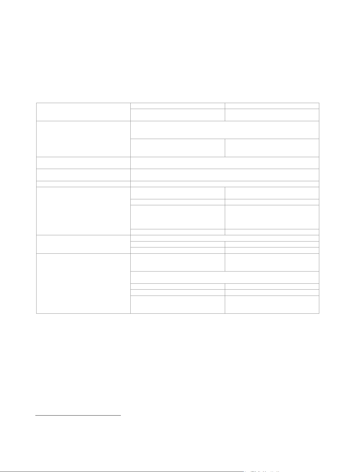
Measured phase noise of wideband analog I/Q outputs; single-ended sine wave with f = 300 MHz
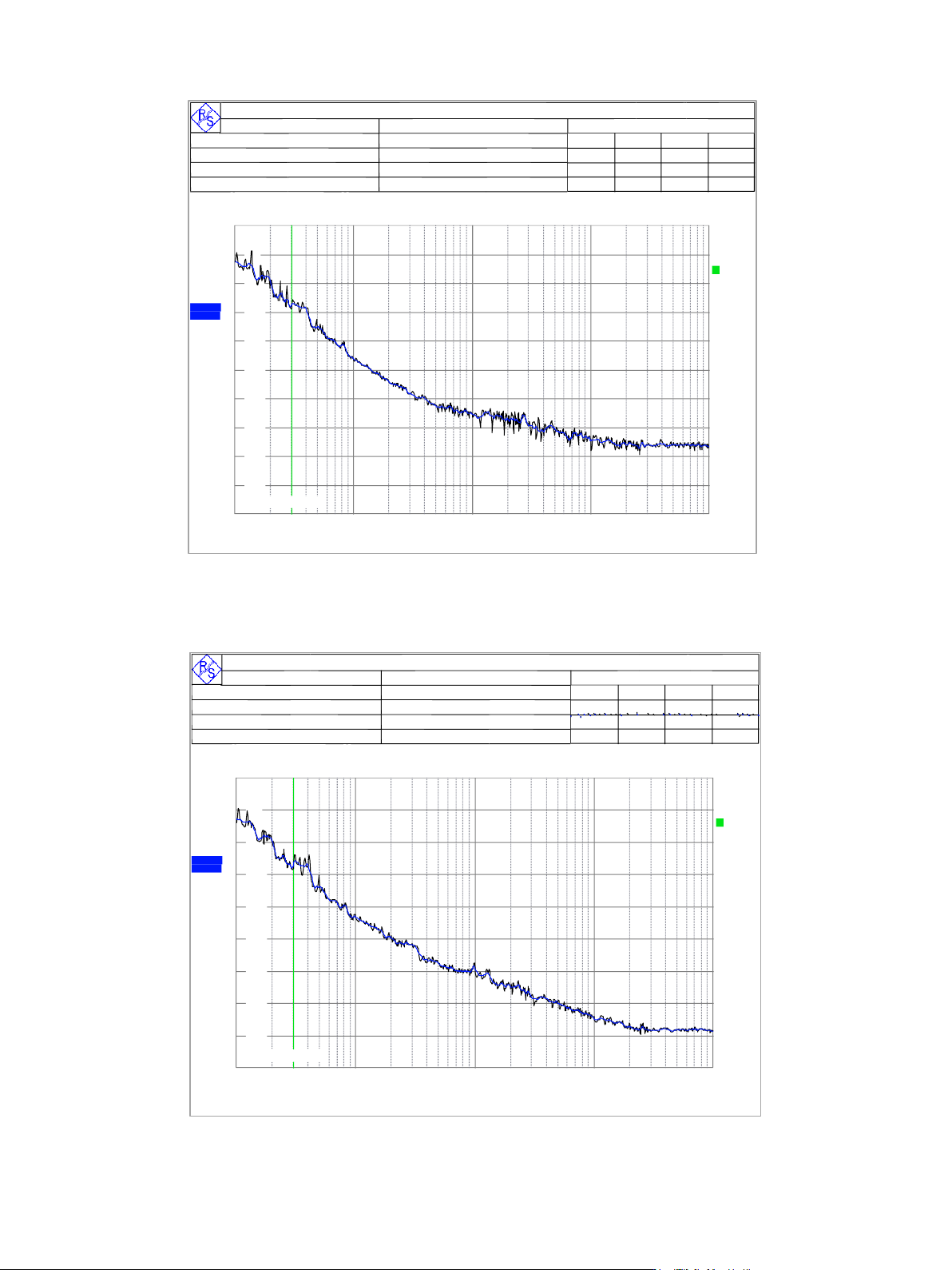
Measured phase noise of wideband analog I/Q outputs; single-ended sine wave with f = 1 GHz
Running ...
R& S FSUP 50 Signal Source A naly zer LO CKED
Set t ings Residual Noise [ T1 w / o spurs] P hase Det ect or +40 dB
Signal Frequenc y: 1 .00 0 0 0 0 GH z I nt P H N (10 0 .0 .. 1 .0 M ) -6 4 .8 dB c
Signal Level: 4 .33 dB m Res idual P M 4 6 .85 0 m°
C ros s C orr M ode H armonic 1 Res idual FM 3 1 .87 3 H z
I nternal Ref T uned I nternal P has e Det RM S J itter 0 .1 3 0 1 ps
P has e N ois e [dBc /H z]
RF A tten 5 dB
T op -7 0 dB c/H z
1 kHz
10 kHz
100 kHz
100 Hz
1 MHz
-150
-140
-130
-120
-110
-100
-90
-80
LoopBW 300 Hz
1 CLRW R
SMTH 1%
2 CLRW R
A
SPR OFF
TH 0dB
Frequency Offset
SMB100A Ser.No 175321
Date: 31.MAR.2003 05:57:49
Running ...
R& S FSUP 50 Signal Source A nalyzer LOCKED
Set t ings Residual Noise [ T1 w / o spurs] P hase Det ect or +40 dB
Signal Frequenc y: 3 0 0 .0 00 0 0 5 M H z I nt P H N (1 0 0.0 .. 1.0 M ) -7 4 .6 dBc
Signal Level: 2 .7 1 dBm Res idual P M 15 .15 6 m°
C ros s C orr M ode H armonic 1 Res idual FM 1 2 .7 6 6 H z
I nternal Ref T uned Internal P has e D et RM S J itter 0 .14 0 3 ps
P has e N ois e [dBc /H z]
RF A tten 5 dB
T op -8 0 dBc /H z
1 kHz
10 kHz
100 kHz
100 Hz
1 MHz
-170
-160
-150
-140
-130
-120
-110
-100
-90
LoopBW 300 Hz
1 CLRW R
SMTH 1%
2 CLRW R
A
SPR OFF
TH 0dB
Frequency Offset
SMB100A Ser.No 175321
Date: 31.MAR.2003 05:55:42
Version 27.00, October 2024
Rohde & Schwarz R&S
®
SMW200A Vector Signal Generator 53
Digital baseband inputs/outputs for wideband baseband
Depending on the installed software and hardware options, the R&S
®
SMW200A is able to receive digital baseband signals and output
digital baseband signals. The digital I/Q input/output can be used for the lossless connection of the R&S
®
SMW200A to the digital I/Q
input/output of other Rohde & Schwarz instruments.
Digital baseband outputs: At least one R&S
®
SMW-K19 option must be installed. Digital baseband outputs can be used either on signal
path A or B with one R&S
®
SMW-K19 option. For digital baseband outputs to be used on signal paths A and B simultaneously,
two R&S
®
SMW-K19 must be installed. To enable two or more digital baseband outputs in multichannel or other advanced modes,
two R&S
®
SMW-K19 must be installed.
The R&S
®
SMW-K19 option requires R&S
®
SMW-B13XT with DACW board revision 4.00 or higher.
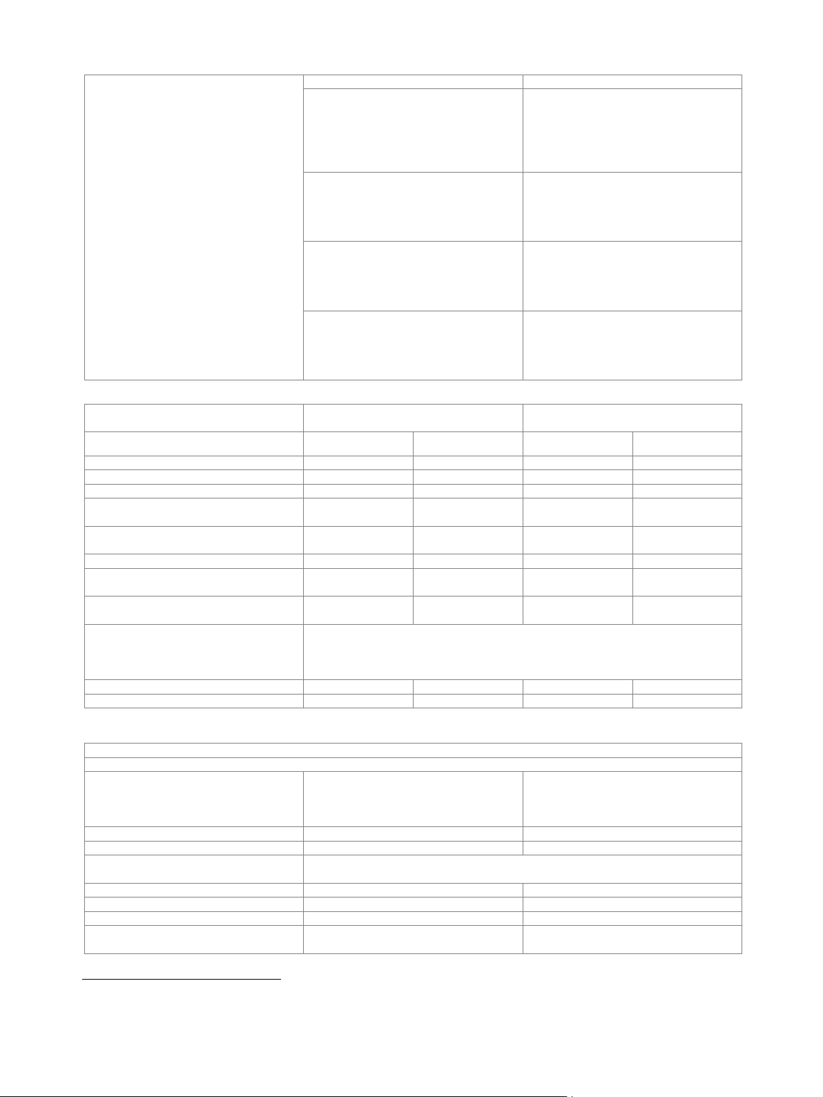
Signal outputs
system configuration mode: standard
analog only, digital only (HS
17
)
system configuration mode: advanced
18
analog and digital, analog and digital (HS),
digital only (HS)
Digital only (HS)
The streams are output via the digital I/Q outputs only (HS DIG I/Q interface standard).
Analog I/Q outputs are not available. External modulation signals can be output via the
RF outputs (I/Q modulation mode: external wideband I/Q).
with R&S
®
SMW-K551 installed and
system configuration mode: advanced
The instrument runs at reduced speed,
depending on the device connected to the
digital I/Q output (slow I/Q).
Analog and digital
The instrument runs in regular operating mode, both analog and digital outputs
(DIG I/Q interface standard) are available.
Analog and digital (HS)
The instrument runs in regular operating mode, both analog and digital outputs
(HS DIG I/Q interface standard) are available.
Analog only
The instrument runs in regular operating mode, only analog outputs are available.
Number of digital outputs
according to selected system configuration
(see table below)
signal outputs: digital only (HS)
maximum 2 (on R&S
®
SMW-B13XT)
signal outputs: analog and digital
maximum 8 (on R&S
®
SMW-B13XT and
R&S
®
SMW-B15) depending on
entities · RX antennas of MIMO/SIMO
configuration
signal outputs: analog and digital (HS)
maximum 2 (on R&S
®
SMW-B13XT)
Number of streams per output
signal outputs: digital only (HS)
system configuration mode: standard
1 to 2
system configuration mode: advanced
1 to 8
Number of streams per input
system configuration mode: standard;
signal outputs: analog only,
HS DIG I/Q
1 to 2
system configuration mode: advanced; signal outputs: analog and digital,
200 MHz, interface either DIG I/Q or HS DIG I/Q
HS DIG I/Q
1 to 2
DIG I/Q
1 to 2
system configuration mode: advanced;
signal outputs: analog and digital,
400 MHz or 800 MHz, HS DIQ I/Q
1 to 2
17
HS = high-speed.
18
The following functions are not available in advanced system configuration mode: analog modulation, modulation sources for analog modulation,
envelope tracking, AM/AM, AM/PM predistortion, Digital Doherty.
Version 27.00, October 2024
54 Rohde & Schwarz R&S
®
SMW200A Vector Signal Generator
Bandwidth (RF)
general
according to selected system configuration
system configuration mode: standard
bandwidth of wideband baseband
generator (see section Wideband
baseband generator, specification for
R&S
®
SMW-B9 option) or maximum
specified bandwidth (RF) of the selected
interface, whichever is smaller
system configuration mode: advanced
200 MHz or maximum specified bandwidth
(RF) of the selected interface, whichever is
smaller (see section Multichannel, MIMO,
fading and noise, specifications for
R&S
®
SMW-K75/-K821 options)
with R&S
®
SMW-K822 option
400 MHz or maximum specified bandwidth
(RF) of the selected interface, whichever is
smaller (see section Multichannel, MIMO,
fading and noise, specifications for
R&S
®
SMW-K75/-K821 options)
with R&S
®
SMW-K823 option
800 MHz or maximum specified bandwidth
(RF) of the selected interface, whichever is
smaller (see section Multichannel, MIMO,
fading and noise, specifications for
R&S
®
SMW-K75/-K821 options)
Minimum required R&S
®
SMW200A
options
Digital I/Q inputs
Digital I/Q outputs
Interface standard
DIG I/Q
HS DIG I/Q
DIG I/Q
HS DIG I/Q
R&S
®
SMW-B13XT + 1 × R&S
®
SMW-K19
–
–
1
1
R&S
®
SMW-B13XT + 2 × R&S
®
SMW-K19
–
–
2
2
1 × R&S
®
SMW-B9 + R&S
®
SMW-B13XT
1
1
–
–
1 × R&S
®
SMW-B9 + R&S
®
SMW-B13XT +
1 × R&S
®
SMW-K19
1
1
1
1
1 × R&S
®
SMW-B9 + R&S
®
SMW-B13XT +
2 × R&S
®
SMW-K19
1
1
2
2
2 × R&S
®
SMW-B9 + R&S
®
SMW-B13XT
2
2
–
–
2 × R&S
®
SMW-B9 + R&S
®
SMW-B13XT +
1 × R&S
®
SMW-K19
2
2
1
1
2 × R&S
®
SMW-B9 + R&S
®
SMW-B13XT +
2 × R&S
®
SMW-K19
2
2
2
2
2 × R&S
®
SMW-B9 +
4 × R&S
®
SMW-B15 + R&S
®
SMW-B13XT +
2 × R&S
®
SMW-K19
depends on selected system configuration
(for required additional options for specific system configurations, see section
Multichannel, MIMO, fading and noise, specifications for R&S
®
SMW-K74, -K75, -K76
options)
2×1×1
2
2
2
2
other
–
–
up to 8
2
Output parameters
DIG I/Q interface
Interface
Standard
DIG I/Q, in line with
R&S
®
Digital I/Q Interface PAD-R
19
,
I/Q data and control signals, data and
interface clock
Level
LVDS
Connector
26-pin MDR
I/Q sample rate
With source "user-defined", the sample rate must be entered via the parameter
"sample rate".
Source
user-defined
Sample rate
250 MHz
Resolution
source: user-defined
0.001 Hz
Frequency uncertainty
source: user-defined
< (1 · 10
−12
+ relative deviation of
reference frequency) · sample rate (nom.)
19
R&S
®
Digital I/Q Interface PAD-R is a Rohde & Schwarz internal company guideline for the transmission of digital I/Q data. It is supported by a wide
range of signal generators, signal analyzers and radio communication testers.