SMW200A_specs_en_3606-8037-22_v2700.pdf - 第59页
Version 27.00, October 2024 Rohde & Schwar z R&S ® SMW200A Vec tor Signal Generator 59 Single carrier delay Setting range 0 s to 1 s Setting resolution 1 ns ARB Ethernet uploa d (R&S ® SMW -K 507 option) ARB …

Version 27.00, October 2024
58 Rohde & Schwarz R&S
®
SMW200A Vector Signal Generator
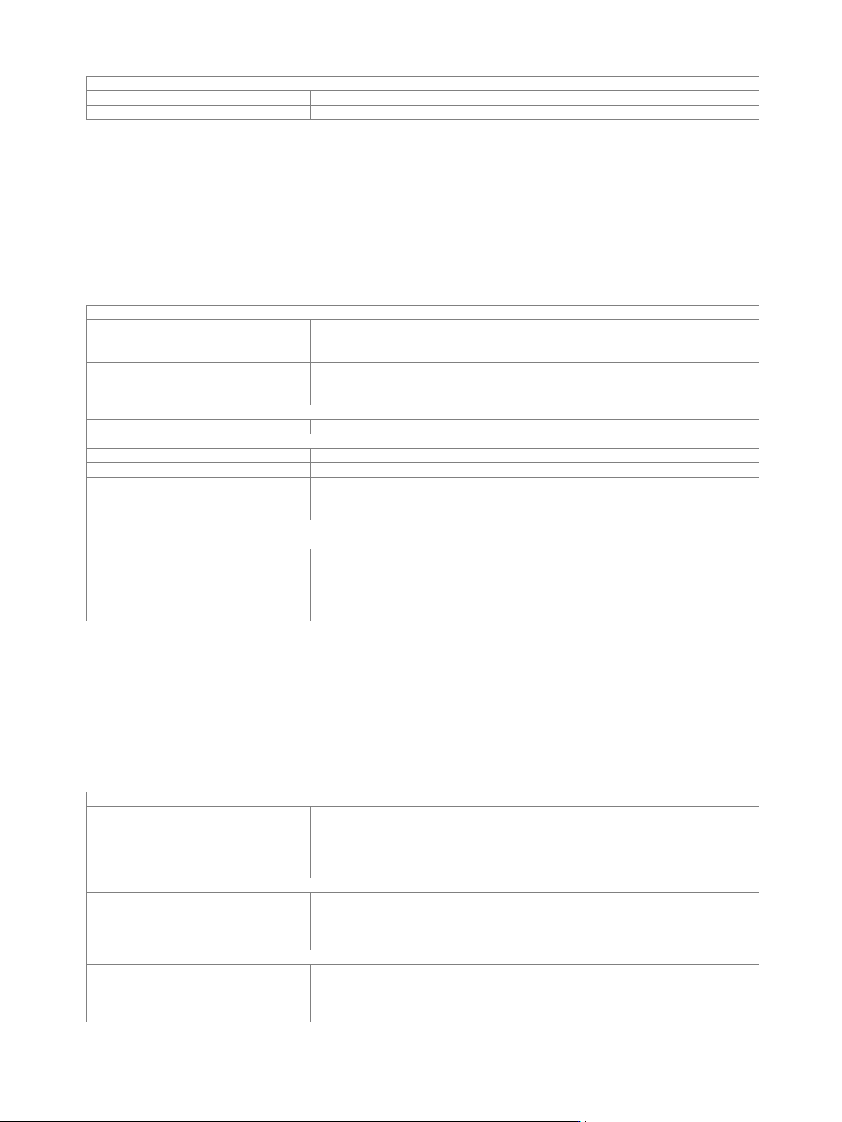
The signal is started only when a trigger
event occurs. The signal is generated
once.
single
External trigger input
selectable from USER 1, 2, 3 on front
panel, or USER 4, 5, 6 on rear panel
Connector type
USER 1, 2, 3 on front panel,
USER 4, 5, 6 on rear panel
BNC female
Input level
0 V to 3 V (nom.)
Threshold
USER 1, 2, 3
settable from 0.1 V to 2.0 V
USER 4, 5, 6
settable from 0.1 V to 2.0 V
Input damage voltage
–0.5 V, 3.8 V
Input impedance
selectable
1 kΩ or 50 Ω (nom.)
Trigger jitter
±1.67 ns
External trigger delay
Setting range
0 sample to 2.147 · 10
9
sample
Setting resolution
0.4 ns
External trigger inhibit
Setting range
0 sample to
(21.47 s · sample rate) sample
Setting resolution
1 sample
External trigger pulse width
> 7.5 ns
Marker signals
Number of marker signals
3
Operating modes
unchanged, restart, pulse, pattern, ratio
Marker outputs
selectable from USER 1, 2, 3 on front
panel or USER 4, 5, 6 on rear panel
Connector type
USER 1, 2, 3 on front panel,
USER 4, 5, 6 on rear panel
BNC female
Level
LVTTL
Marker delay
Setting range
0 sample to (waveform length – 1) sample
Setting resolution
1 sample
Marker duration
Minimum value
sample rate ≤ 300 Msample/s
1 sample
300 Msample/s < sample rate ≤
600 Msample/s
2 sample
600 Msample/s < sample rate ≤
1200 Msample/s
4 sample
1200 Msample/s < sample rate ≤
2400 Msample/s
8 sample
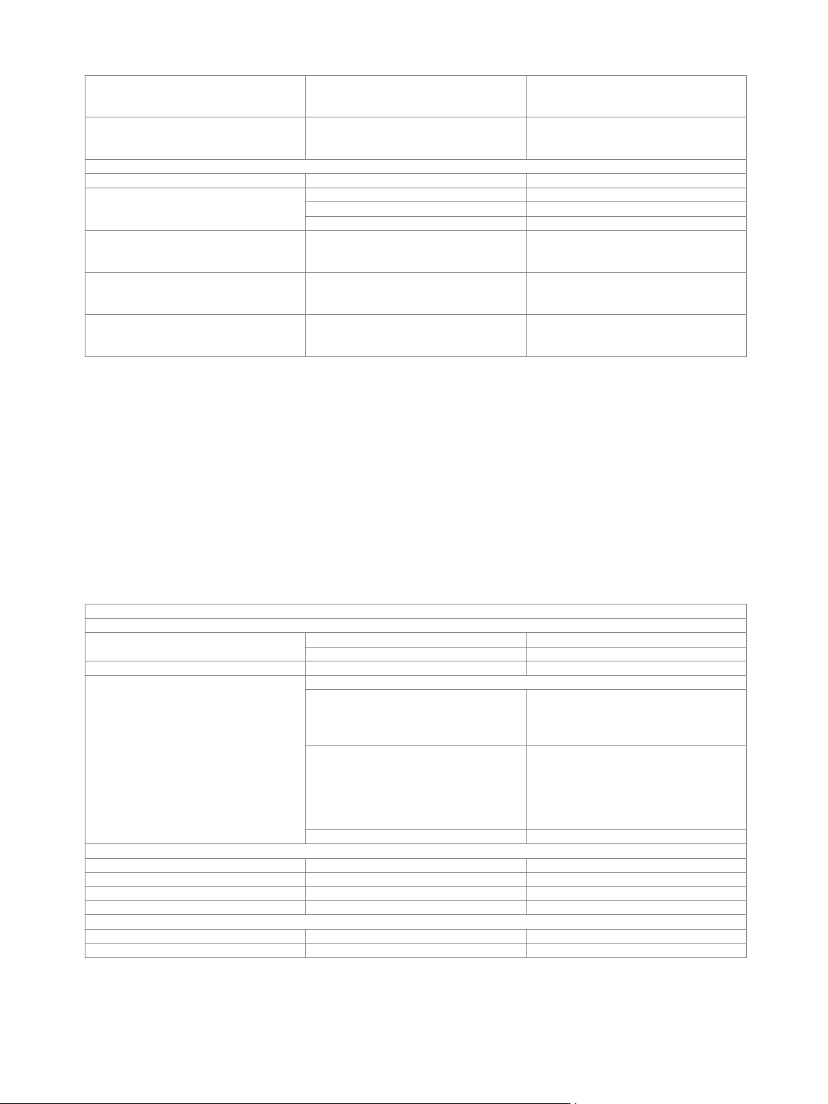
Multisegment waveform mode
Number of segments
1 to 1024
Changeover modes
GUI, remote control
Extended trigger modes
same segment, next segment, next
segment seamless, sequencer
Seamless changeover
output up to end of current segment,
followed by changeover to next segment
Sequencer play list length
max. 1024
Sequencer segment repetitions
max. 1 048 575
Multicarrier waveform mode
Number of carriers
max. 512
Total RF bandwidth
max. 500 MHz
with R&S
®
SMW-K525 option
max. 1000 MHz
with R&S
®
SMW-K527 option
max. 2000 MHz
Carrier spacing
Setting range
depends on number of carriers and signal
RF bandwidth
Setting resolution
0.01 Hz
Crest factor modes
maximize, minimize, off
Signal period modes
longest file, shortest file, user (max. 1 s)
Single carrier gain
Setting range
–80 dB to 0 dB
Setting resolution
0.01 dB
Single carrier start phase
Setting range
0° to 360°
Setting resolution
0.01°
Version 27.00, October 2024
Rohde & Schwarz R&S
®
SMW200A Vector Signal Generator 59
Single carrier delay
Setting range
0 s to 1 s
Setting resolution
1 ns
ARB Ethernet upload (R&S
®
SMW-K507 option)
ARB Ethernet upload is a sub mode of arbitrary waveform mode, see section Wideband baseband generator (R&S
®
SMW-B9 option) –
arbitrary waveform mode. This feature allows a fast upload und playback of waveform I/Q samples from an external source via UDP
over a QSFP+ LAN interface into a Rohde & Schwarz signal generator (R&S
®
SMW200A).
The waveform parameter and I/Q samples are transferred using special transmission commands (Rohde & Schwarz upload protocol,
see K507 user manual).
At least one R&S
®
SMW-B9 wideband baseband generator option must be installed. If two R&S
®
SMW-B9 options are installed (signal
paths A and B), the ARB Ethernet upload can be used either on signal path A or B with one R&S
®
SMW-K507 option. For simultaneous
usage on signal paths A and B, two R&S
®
SMW-K507 options must be installed.
ARB Waveform
File size, technical specification
see section Wideband baseband
generator (R&S
®
SMW-B9 option) –
arbitrary waveform mode
File generation
see R&S
®
SMW200A user manual, section
Using the Arbitrary Waveform Generator
(ARB)
Upload transmission protocol
R&S
®
ARB upload protocol
see K507 user manual
Marker signals
Number of marker signals
3
Operating modes
waveform (unchanged), restart
Marker outputs
see section Wideband baseband
generator (R&S
®
SMW-B9 option) –
arbitrary waveform mode
Interface parameters
LAN interface
Connector
HS/DIGIQ 1, 2 on rear panel
QSFP+ (note the recommended extras
below)
Protocol
UDP over Ethernet
Data rate
10 Gigabit Ethernet or 40 Gigabit Ethernet
can be configured in user interface
10 Gbit/s, 40 Gbit/s
Extended sequencing (R&S
®
SMW-K502 option)
The R&S
®
SMW-K502 option enables waveform sequencing and real-time signal generation for ultra long playtime. Waveform
variations such as offset frequency, amplitude and phase are calculated in real-time and do not require precalculated waveforms.
The extended sequencing is controlled by the external R&S
®
Pulse Sequencer Software, a powerful software tool for simulating
complex sequencing scenarios.
At least one R&S
®
SMW-B9 option (wideband baseband generator) must be installed. If two R&S
®
SMW-B9 options are installed (signal
paths A and B), extended sequencing can be used either on signal path A or B with one R&S
®
SMW-K502 option. For extended
sequencing to be used simultaneously on signal paths A and B, two R&S
®
SMW-K502 options must be installed.
General settings
Modes
controlled by external
R&S
®
Pulse Sequencer Software
(R&S
®
SMW-K300 required)
pulse sequencer
Pulse sequencer mode
see R&S
®
Pulse Sequencer Software
specifications (PD 3607.1388.22)
Waveform segments
Segment length
1 sample to 64 Msample
Minimum memory allocation
64 sample
Maximum number of segments
depends on segment lengths and
baseband generator ARB memory size
Waveform sequences
Sequencing
continuously repeating
Maximum number of segments per
sequence
depends on segment lengths and
baseband generator ARB memory size
Maximum number of segment repetitions
2
32
Version 27.00, October 2024
60 Rohde & Schwarz R&S
®
SMW200A Vector Signal Generator
Clock
see section Wideband baseband
generator (R&S
®
SMW-B9 option) –
arbitrary waveform mode
Triggering
see section Wideband baseband
generator (R&S
®
SMW-B9 option) –
arbitrary waveform mode
Marker signals
Number of marker signals
3
Operating modes
marker at every start of sequence
restart
marker 1 embedded in waveform
unchanged
marker at every pulse
pulse
Marker outputs
see section Wideband baseband
generator (R&S
®
SMW-B9 option) –
arbitrary waveform mode
Marker delay
see section Wideband baseband
generator (R&S
®
SMW-B9 option) –
arbitrary waveform mode
Marker duration
see section Wideband baseband
generator (R&S
®
SMW-B9 option) –
arbitrary waveform mode
Real-time control interface (R&S
®
SMW-K503/-K504 options)
The R&S
®
SMW-K503/-K504 option enhances the R&S
®
SMW-B9 wideband baseband generator option by adding a dedicated 1 Gbit/s
LAN interface for pulse descriptor word (PDW) streaming. PDWs are streamed via the external LAN interface to control a real-time
sequencer on the R&S
®
SMW-B9. Either a precalculated waveform can be played back or certain signals such as rectangular pulses,
Barker codes and chirps can be generated in real time.
In addition to these different signal types, the interface provides agile switching of frequency, phase and amplitude. These variations
are calculated in real time.
The real-time control interface is controlled by an external simulator that streams the PDWs in a proprietary Rohde & Schwarz format.
At least one R&S
®
SMW-B9 wideband baseband generator option and one R&S
®
SMW-K502 option must be installed. If two
R&S
®
SMW-B9 options and two R&S
®
SMW-K502 options are installed (signal paths A and B), the real-time control interface can be
used either on signal path A or B with R&S
®
SMW-K503 or -K504 option. For simultaneous usage on signal paths A and B, two
R&S
®
SMW-K503/-K504 options must be installed. The R&S
®
SMW-K504 option increases the maximum PDW rate from 1 MPDW to
2 MPDW. Each R&S
®
SMW-K504 option requires an R&S
®
SMW-K503 option to be installed.
PDW parameters
PDW format
PDW
variant no. 1
32 byte fixed length
variant no. 2
32/48 byte fixed length
CNTRL PDW
16 byte fixed length
Controllable parameters
PDW
variant no. 1
time of arrival, frequency offset, amplitude
offset, phase offset, real-time modulation
on pulse (MOP, see real-time MOP types
below), I/Q waveform index
variant no. 2
time of arrival, rise time, fall time, edge
type (linear, cosine), repetitions (in burst
mode), frequency offset, amplitude offset,
phase offset, real-time modulation on
pulse (MOP, see real-time MOP types
below), I/Q waveform index
CNTRL PDW
absolute amplitude, absolute frequency
Setting granularity
Time
417 ps
Amplitude
16 bit (voltage based)
Phase
< 0.01°
Frequency
0.58 Hz
I/Q segments
Maximum individual segments
16 777 216
Length granularity
32 sample