00198706-01_AI_Stationaere_Kamera_25_33_GigE_SXV3_DE_EN.pdf - 第60页
1 Introduction 1.4 Staff qualifications and training 60 Assembly Instructions / Montageanleitung SIPLACE SX1/SX2 V3 Stationäre Kamera Typ 25/33 (GigE) Stationary Camera Type 25/33 (GigE) 03/2021

1 Introduction
1.4 Staff qualifications and training
Assembly Instructions / Montageanleitung SIPLACE SX1/SX2 V3 Stationäre Kamera Typ 25/33 (GigE) Stationary
Camera Type 25/33 (GigE) 03/2021
59
1.3.3.5 Dispatching ESD modules
► Always store modules and components in conductive packaging (e.g. metallized plastic bags
or metal sleeves) and dispatch them in conductive packaging
► If the packaging is not conductive, place the modules in a conductive envelope before pack-
aging. Use conductive expanded rubber, ESD bags, domestic aluminum foil or paper, for
example. NEVER use plastic bags or film.
► If the module has integral batteries, ensure that the conductive packaging does not touch or
short circuit the battery terminals and, if necessary, first cover the terminals with insulating
tape or material.
1.3.4 Release History
Document
SIPLACE SX1/SX2 V3
Stationary camera type 25/33 (GigE)
Assembly Instructions
Release Amendments
03/2021 Initial release
1.4 Staff qualifications and training
Qualified or adequately trained personnel means that these people are familiar with the setting up,
operation and maintenance of the machine and the add-on devices and are suitably qualified, e.g.:
●
Have been trained, instructed or authorized to switch on and off, isolate, earth and identify
electrical circuits and system components in accordance with normal safety standards.
●
Have been trained or instructed in the upkeep and use of appropriate safety equipment in
accordance with normal safety standards.

1 Introduction
1.4 Staff qualifications and training
60 Assembly Instructions / Montageanleitung SIPLACE SX1/SX2 V3 Stationäre Kamera Typ 25/33 (GigE) Stationary
Camera Type 25/33 (GigE) 03/2021
2 Brief Description
2.1 Overview of component cameras
Assembly Instructions / Montageanleitung SIPLACE SX1/SX2 V3 Stationäre Kamera Typ 25/33 (GigE) Stationary
Camera Type 25/33 (GigE) 03/2021
61
2 Brief Description
2.1 Overview of component cameras
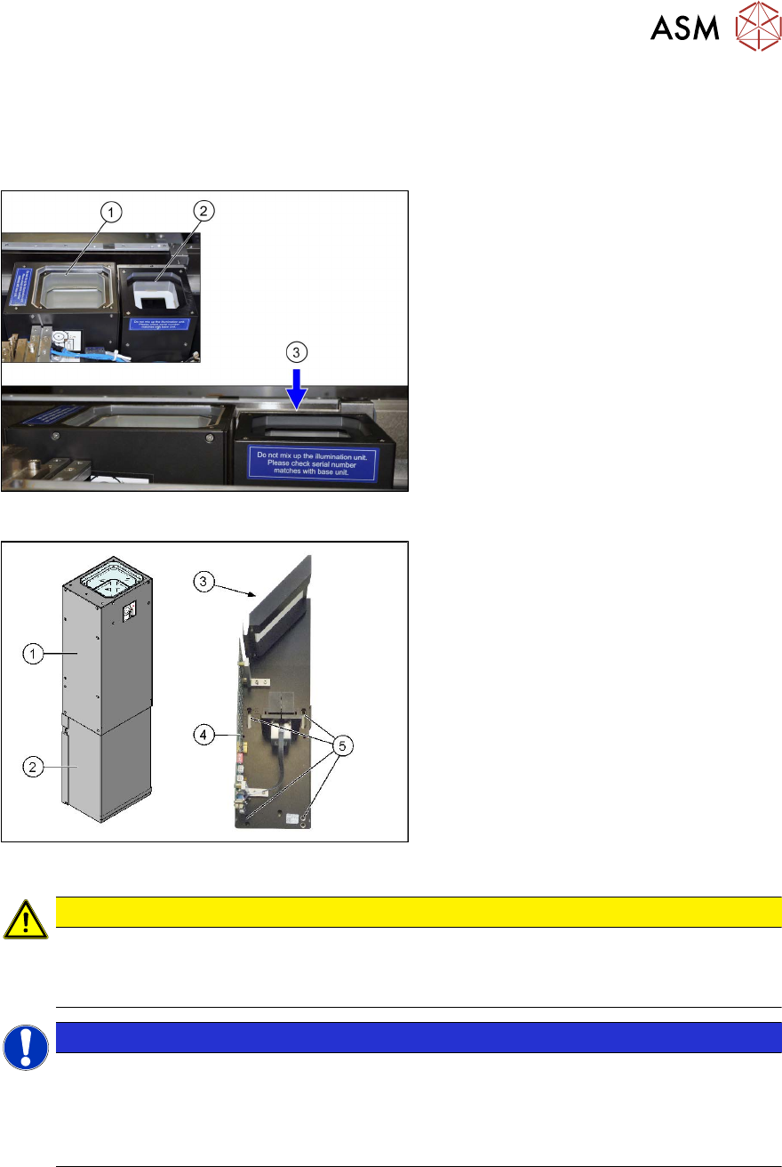
Fig.6: Installation position
Installation position
1. Stationary camera, type 33 (IC camera)
2. Stationary camera, type 25 (FC cam-
era)
3. Installation height for FC camera (cam-
era top edge approx. 5 mm under the
upper edge of the board conveyor)
Fig.7: Camera structure
Camera structure
Component camera, stationary P&P (type
33) 55x45
1. Upper section of camera (illumination
unit)
2. Lower section of camera
3. Glass plate
4. Camera electronics
5. Holes for fastening screws
CAUTION
Do not hold or carry the camera by its electronics unit
The camera electronics assembly is a sensitive unit and can be easily damaged.
► Only hold or carry the camera by its metal frame.
NOTICE
The camera upper section has a fixed assignment to the camera lower section.
The camera upper section may not be used with another camera lower section. Both the
upper and lower sections are mechanically and electrically coordinated and may not be ex-
changed for use with other cameras. The serial and version numbers of the top and bottom
sections of the camera must be identical.