00198706-01_AI_Stationaere_Kamera_25_33_GigE_SXV3_DE_EN.pdf - 第73页
3 Installation 3.6 Electrical connections Assembly Instructions / Montageanleitung SIPLACE SX1/SX2 V3 Stationäre Kamera Typ 25/33 (GigE) Stationary Camera Type 25/33 (GigE) 03/2021 73 3.5.3 Fitting the FC camera and supp…
3 Installation
3.5 Fitting the cameras
72 Assembly Instructions / Montageanleitung SIPLACE SX1/SX2 V3 Stationäre Kamera Typ 25/33 (GigE) Stationary
Camera Type 25/33 (GigE) 03/2021
3.5.2 Fitting the IC camera
CAUTION
Observe the installation height
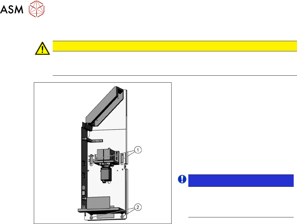
When fitting the camera, observe the correct installation height. Otherwise there is a risk of
head crash!
Fig.14: Lower section of camera
► Screw the two top fastening screws
loosely into the support plate assembly
onto which the camera will be fitted
later on. The screws should be
tightened enough to still allow the cam-
era to be easily hooked in.
► Carefully hook the top screw holes on
the lower section of the camera(1)
onto the fastening screws.
► Fix the lower section of the camera with
two screws to the lower screw open-
ings (2)
.
NOTICE!
Installation height
The correct installation height is de-
termined by the thread in the support
plate assembly.
.
► Tighten all four fastening screws.
The lower section of the camera has now
been fixed into place.
3 Installation
3.6 Electrical connections
Assembly Instructions / Montageanleitung SIPLACE SX1/SX2 V3 Stationäre Kamera Typ 25/33 (GigE) Stationary
Camera Type 25/33 (GigE) 03/2021
73
3.5.3 Fitting the FC camera and support plate
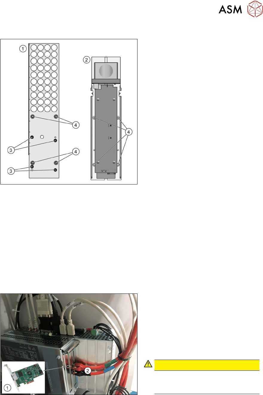
Fig.15: Support plate FC [03077911‑xx]
1. Support plate FC [03077911‑xx]
2. Lower part of FC camera
3. Four screws [03045087‑xx]
(DIN912-M6x12-A2-70)
4. Four screws [03042574‑xx]
(ISO4762-M6x20-A2-70)
●
Two threaded pins [03106014‑xx]
(DIN‑EN‑ISO4026-M6x50‑45H)
► Fit the support plate(1) to the support
plate with four screws(3)
.
The FC camera(2) is fixed into place with
four screws(4)
. For easier installation, pro-
ceed as follows:
► Rotate the two threaded pins into the top two positions.
► Fit the bottom section of the FC camera onto the two threaded pins.
► Fasten the camera at the bottom with two screws.
► Remove the two threaded pins.
► Fasten the camera at the top with two screws.
3.6 Electrical connections
Also observe the detailed circuit diagrams for your machine:
●
Detailed circuit diagrams folder for SIPLACE SX1/SX2V3 (fromRxxxx)
[DEEN:00198680‑xx]
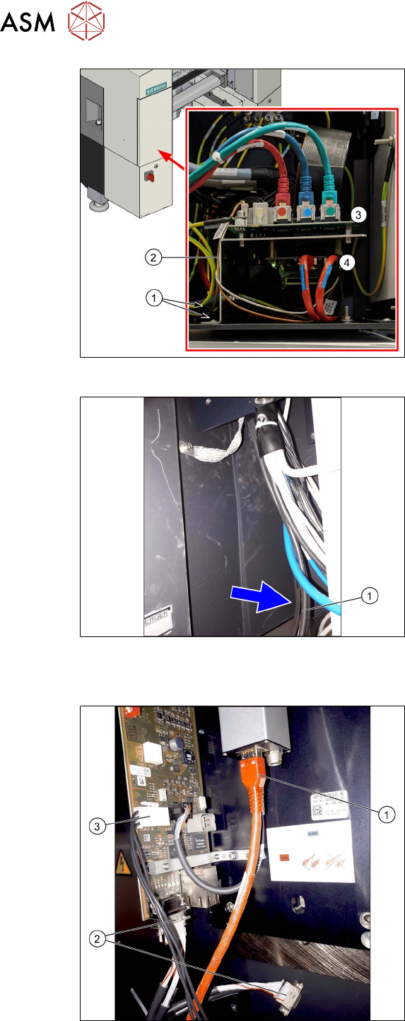
Fig.16: GigE ethernet adapter in the BoxPC
1. GigE ethernet adapter PCI-E I350 T2
V2 BLK [03115569‑xx]
2. GigE cable:
Gantry/location 1: X1
Gantry/location 2: X2
► Check the cabling on the BoxPC.
CAUTION!
Never insert a LAN cable into the
GigE card.
This could damage the GigE card.
.
3 Installation
3.6 Electrical connections
74 Assembly Instructions / Montageanleitung SIPLACE SX1/SX2 V3 Stationäre Kamera Typ 25/33 (GigE) Stationary
Camera Type 25/33 (GigE) 03/2021
Fig.17: Overview of trailing cable interface
1. Screws fastening the mount (front and
back)
2. Mount
3. Trailing unit interface
4. Vision Base Interface (VBI) (on the un-
derside of the mount)
The trailing cable interface for gantry 1 is
located in sector 1.
The trailing cable interface for gantry 2 (only
SIPLACE SX 1 prepared" and SX2) is loc-
ated in sector 3.
Fig.18: Connecting cable
► Find the connection cable(1). This is
either on the left or right of the cable
tree, depending on the location.
Electrical connections for IC camera
Fig.19: IC camera
1. Camera cable
Location 1: CAT6 [03221649‑xx]
Location 2: CAT6 [03221651‑xx]
2. CAN bus cable
MCAN cable [03099372‑xx] for IC and
FC camera
MCAN2 one each for location 1 and 2
3. Power supply cable [03200832‑xx]
one each for location 1 and 2
When only one stationary camera is used,
the camera cable, the CAN bus cable and
the power supply cable are connected dir-
ectly.