00198706-01_AI_Stationaere_Kamera_25_33_GigE_SXV3_DE_EN.pdf - 第89页
4 Appendix 4.1 Excerpts from the Service Manual Assembly Instructions / Montageanleitung SIPLACE SX1/SX2 V3 Stationäre Kamera Typ 25/33 (GigE) Stationary Camera Type 25/33 (GigE) 03/2021 89 Fig.38: Table position 1 Down…
4 Appendix
4.1 Excerpts from the Service Manual
88 Assembly Instructions / Montageanleitung SIPLACE SX1/SX2 V3 Stationäre Kamera Typ 25/33 (GigE) Stationary
Camera Type 25/33 (GigE) 03/2021
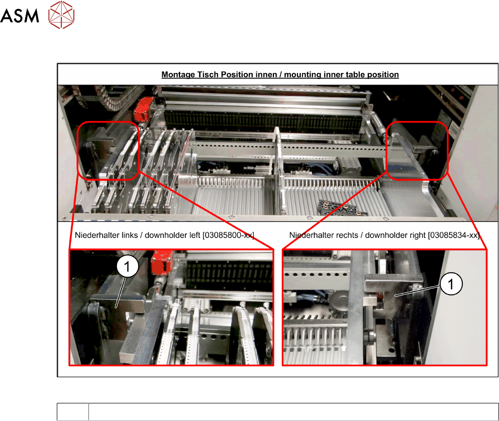
Checking the downholder positions
Fig.37: Table position
1 Docking aid
► Move the component trolley back into the machine.
► The component trolley height must be adjusted so that the side rails fit into the recess on the
docking aid(1)
. (See also Setting the Changeover Table Height)
4 Appendix
4.1 Excerpts from the Service Manual
Assembly Instructions / Montageanleitung SIPLACE SX1/SX2 V3 Stationäre Kamera Typ 25/33 (GigE) Stationary
Camera Type 25/33 (GigE) 03/2021
89
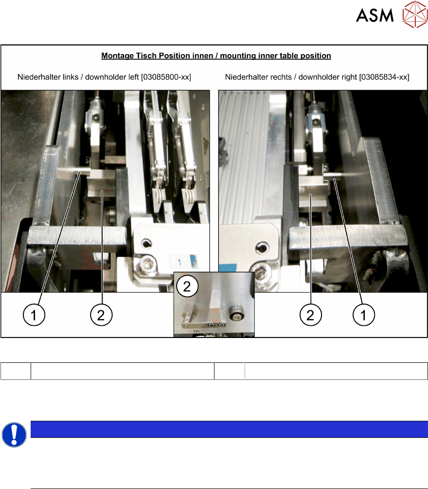
Fig.38: Table position
1 Downholder pin on the docking aid 2 Component trolley downholder
► After pulling the table in through the cylinder, the downholder pin(1) should be up, against the
component trolley downholder(2)
.
NOTICE
Wear
In the event of frequent component trolley cycle changes, these parts may become worn.
Both the downholder pin and the component trolley downholder are available as spare
parts.
4 Appendix
4.2 Description of Boards
90 Assembly Instructions / Montageanleitung SIPLACE SX1/SX2 V3 Stationäre Kamera Typ 25/33 (GigE) Stationary
Camera Type 25/33 (GigE) 03/2021
4.2 Description of Boards
4.2.1 PCBs Stationary Cameras
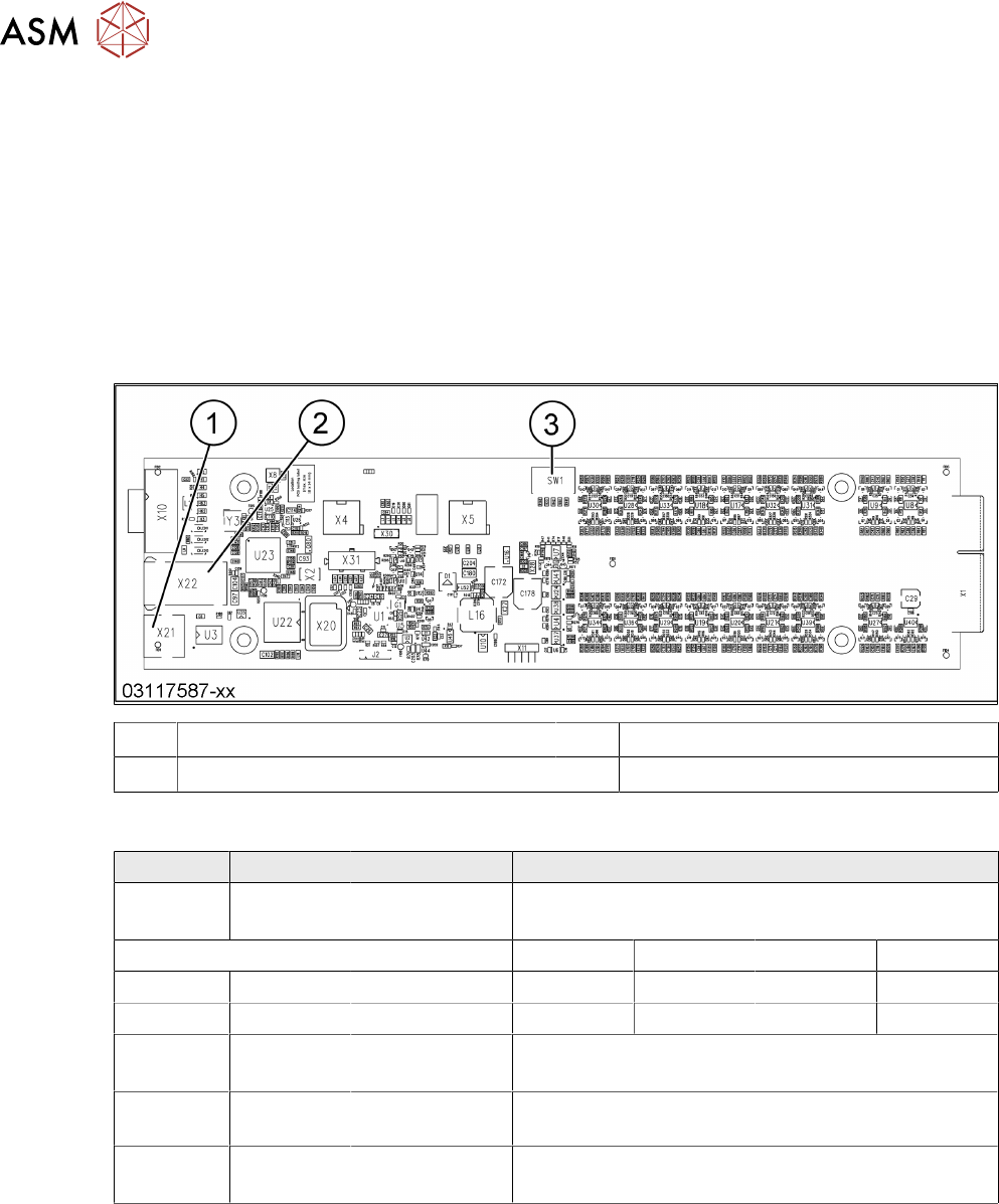
4.2.1.1 Vision LED Controller VLC25/33 GigE DTC
The boards
Vision LED Controller VLC33 GigE DTC [03117981-xx] and
Vision LED Controller VLC25 GigE DTC [03117587-xx]
are identical except for the connectors Stecker X21 and X22. These connectors are only on the
VLC25 board.
The boards are part of the stationary camera SST25/33 GigE.
1 Connector X21 (VLC25 only) 2 Connector X22 (VLC25 only)
3 DIP switch SW1 (see below)
DIP switch S1 [03117587-xx] [03117981-01]
Switch Status Signal name Description
S1.1 OFF VCU_CODE OFF: normal operation
ON: Reset
Location 1 Location 2 Location 3 Location 4
S1.2 ON/OFF *) PORTAL_ID_0 OFF ON OFF ON
S1.3 ON/OFF *) GANTRY_ID_1 OFF OFF ON ON
S1.4 OFF SMD_LED OFF: standard LED
ON: SMD LED
S1.5 OFF CAN_H OFF: with CAN terminator
ON: without CAN terminator
S1.6 ON/OFF CAN_GROUP OFF: FC camera
ON: IC camera
*) Set the location at which the stationary camera is fitted.