00198706-01_AI_Stationaere_Kamera_25_33_GigE_SXV3_DE_EN.pdf - 第64页
2 Brief Description 2.3 Scope of delivery 64 Assembly Instructions / Montageanleitung SIPLACE SX1/SX2 V3 Stationäre Kamera Typ 25/33 (GigE) Stationary Camera Type 25/33 (GigE) 03/2021 2.3 Scope of delivery NOTICE Head ch…
2 Brief Description
2.2 Prerequisites and restrictions
Assembly Instructions / Montageanleitung SIPLACE SX1/SX2 V3 Stationäre Kamera Typ 25/33 (GigE) Stationary
Camera Type 25/33 (GigE) 03/2021
63
2.2 Prerequisites and restrictions
●
The camera design and the assembly procedure for each camera is generally the same for
the individual machines. Any differences will be explicitly indicated in this guide.
●
When using a SIPLACE C&P20x head, make sure that there are no stationary cameras fitted
in the same placement area.
●
You may need to move the COT insert, depending on your machine configuration.
●
If you switch to mixed mode with the SIPLACE SX V3 (SIPLACE C&P20x and CPP), you will
need to fit the SIPLACE CPP in low position and any stationary camera already fitted must be
removed!
WARNING
Head crash risk by changeover to SIPLACE C&P20x head
When changing a placement head from a SIPLACE Twin or CPP to a SIPLACE C&P20x,
the CPP will need to be fitted in the upper position.
Note: the stationary camera has only one position (height of conveyor upper edge) in the
SIPLACE SX V3.
WARNING
Head crash risk by changeover to SIPLACE CPP head
When changing the placement head from a SIPLACE Twin to a SIPLACE CPP, you will
need to install the stationary component camera (type 33, 55x45, digital) in the lower posi-
tion.
NOTICE
FC camera, 3D coplan module and SIPLACE Twin
An FC camera and a 3D coplan module are only possible together with a SIPLACE Twin.
Only one of these options can be fitted at the same location, meaning that either the FC
camera or the 3D coplan module can be used.
2 Brief Description
2.3 Scope of delivery
64 Assembly Instructions / Montageanleitung SIPLACE SX1/SX2 V3 Stationäre Kamera Typ 25/33 (GigE) Stationary
Camera Type 25/33 (GigE) 03/2021
2.3 Scope of delivery
NOTICE
Head change
If you are installing a stationary camera as part of a head or gantry change, please contact
the SIPLACE service team. They can use a configurator to determine and provide you with
the necessary parts.
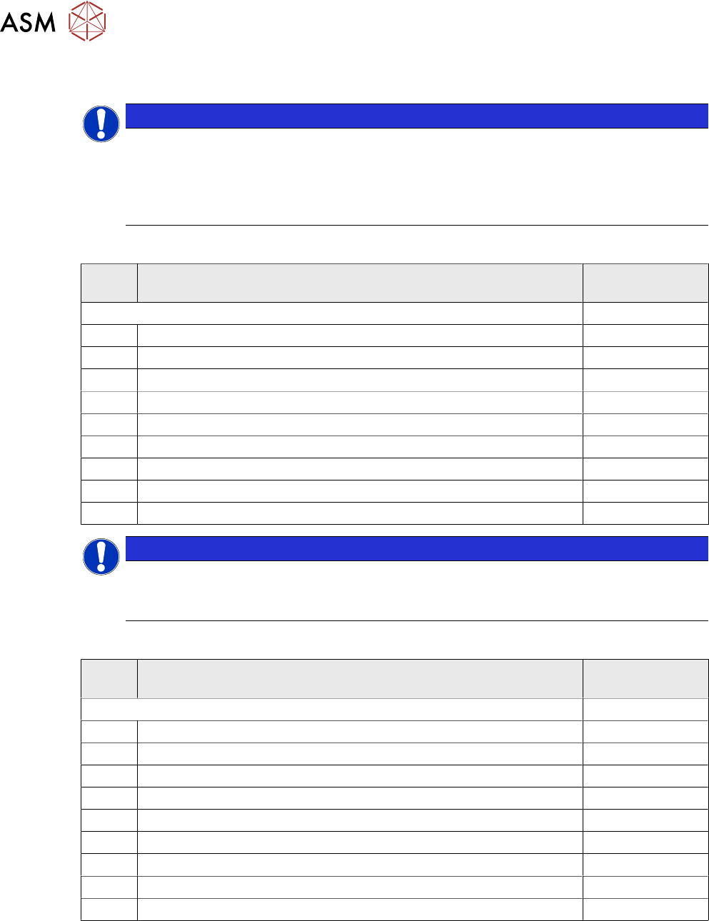
► Head reconfiguration kit SIPLACE SX V3 from R0001, GigE, SAP no. 00588507
IC camera (SST33):
Quant-
ity
Designation Item no.
Upgrade kit for stationary camera type 33 GigE for SIPLACE SX V3 03225370Sxx
1 Component camera, stat. P&P (TYPE33) 55x45 GigE 03105198-xx
4 ISO 4762 - M 6 x 22-A2-70 03043127-xx
1 Support plate assembly SP1 03070836-xx
1 Support plate assembly SP2 03070862-xx
4 ISO 4762 - M 6 x 12-A2-70 03042572-xx
4 ISO 8734 - 5 x 18 - A-ST 03015784-xx
1 Holder for reject bin P001 03063283-xx
2 ISO 4762 - M 6 x 10-A2-70 03042571-xx
1 Reject bin assembly 03072806-xx
NOTICE
When fitting the reject bin with verification query, you will need to order the following addi-
tional package:
► Verify component reject bin, SIPLACE SX1/2 [00519848‑xx]
FC camera (SST25, only for TH/VHF TH):
Quant-
ity
Designation Item no.
Upgrade kit for stationary camera P&P type 25 GigE, SIPLACE SX V3 03222727Sxx
1 Component camera stat. P+P (type25) 16x16 GigE 03105205-01
1 Support plate FC 03077911-01
4 ISO 4762 - M 6 x 20-A2-70 03042574-01
1 Self-adhesive mounting base MB3A 19x19mm 00316830-01
1 Cable ties W = 3.6.mm L = 140.mm TYB-24M 00805141-01
1 Cable, ext. power supply, stat. camera 03105096-01
1 Cable: extension, camera bus IC/FC camera 03106367-01
2 DIN EN ISO 4026 - M6 x 50-45H 03106014-01
1 ISO 8734 - 5 x 18 - A-ST 03015784-01

2 Brief Description
2.4 Tools and Equipment Required
Assembly Instructions / Montageanleitung SIPLACE SX1/SX2 V3 Stationäre Kamera Typ 25/33 (GigE) Stationary
Camera Type 25/33 (GigE) 03/2021
65
2.4 Tools and Equipment Required
●
ESD tape
●
Set of Allen keys
●
Set of screwdrivers
●
Universal pliers
●
Self-adhesive mounting base for cable ties (pack of 10 [03064015-xx])
●
Cable ties, B=2.5mm, L=102mm Panduit (pack of 10 [00308458-xx])
●
Microfiber cloth for cleaning optical assemblies
Service manual for your machine:
●
Service Manual SIPLACE SX1/SX2 V3 [DE:00198707‑xx] [EN:00198708‑xx]
Circuit diagrams for your machine:
●
Detailed circuit diagrams folder for SIPLACE SX1/SX2V3 (fromRxxxx)
[DEEN:00198680‑xx]
NOTICE
Second person
You might find it advisable to enlist the help of a second person for certain tasks.
The following additional tools will also be needed, depending on the camera type:
FC camera (type 25)
●
Long Allen key with T-handle (at least 30 cm) size 6
●
If no stationary camera has been fitted at location 1:
support plate assembly SP1 [03070836-xx]
The camera and reject bin are fitted onto this.
IC camera (type 33)
●
Allen key with T-handle size 5 and 6
●
Calibration tool version 3 [03010565-xx]
●
Assembly instructions "Verify component reject bin SIPLACE SX1/SX2 DE+EN"[00196615-xx]
2.5 Required Working Time
The complete installation will take approx. between 1 and 2 hours. The work time depends primar-
ily on the type of machine, the location and the camera configuration at the location.