00198706-01_AI_Stationaere_Kamera_25_33_GigE_SXV3_DE_EN.pdf - 第61页
2 Brief Description 2.1 Overview of component cameras Assembly Instructions / Montageanleitung SIPLACE SX1/SX2 V3 Stationäre Kamera Typ 25/33 (GigE) Stationary Camera Type 25/33 (GigE) 03/2021 61 2 Brief Description 2.1 …

1 Introduction
1.4 Staff qualifications and training
60 Assembly Instructions / Montageanleitung SIPLACE SX1/SX2 V3 Stationäre Kamera Typ 25/33 (GigE) Stationary
Camera Type 25/33 (GigE) 03/2021
2 Brief Description
2.1 Overview of component cameras
Assembly Instructions / Montageanleitung SIPLACE SX1/SX2 V3 Stationäre Kamera Typ 25/33 (GigE) Stationary
Camera Type 25/33 (GigE) 03/2021
61
2 Brief Description
2.1 Overview of component cameras
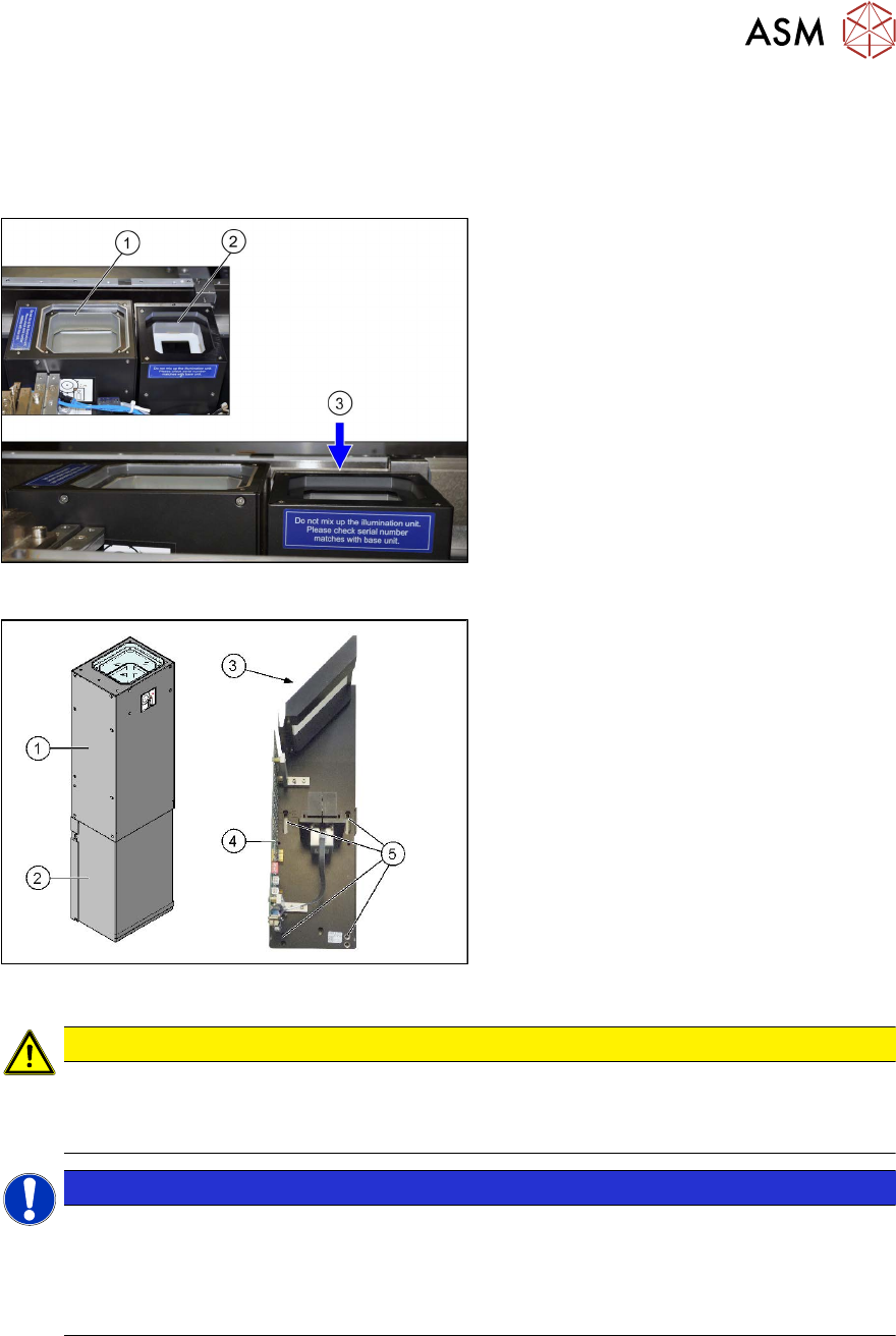
Fig.6: Installation position
Installation position
1. Stationary camera, type 33 (IC camera)
2. Stationary camera, type 25 (FC cam-
era)
3. Installation height for FC camera (cam-
era top edge approx. 5 mm under the
upper edge of the board conveyor)
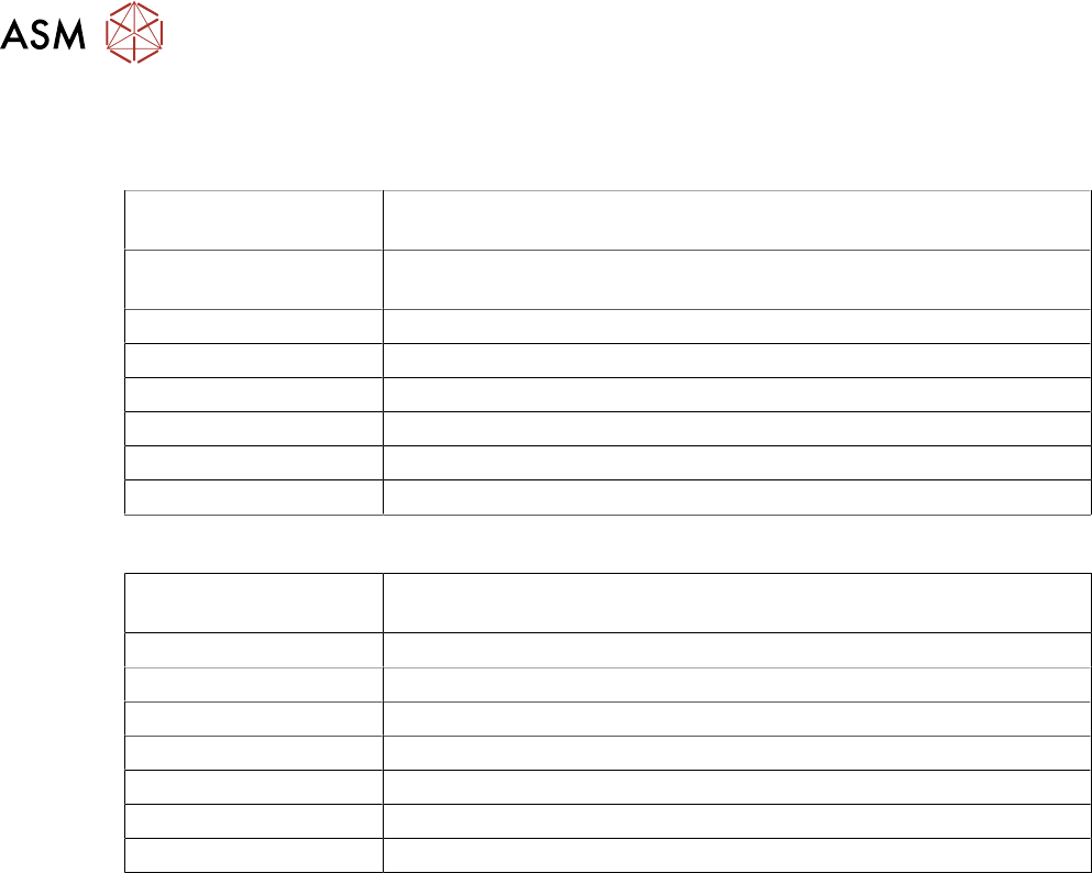
Fig.7: Camera structure
Camera structure
Component camera, stationary P&P (type
33) 55x45
1. Upper section of camera (illumination
unit)
2. Lower section of camera
3. Glass plate
4. Camera electronics
5. Holes for fastening screws
CAUTION
Do not hold or carry the camera by its electronics unit
The camera electronics assembly is a sensitive unit and can be easily damaged.
► Only hold or carry the camera by its metal frame.
NOTICE
The camera upper section has a fixed assignment to the camera lower section.
The camera upper section may not be used with another camera lower section. Both the
upper and lower sections are mechanically and electrically coordinated and may not be ex-
changed for use with other cameras. The serial and version numbers of the top and bottom
sections of the camera must be identical.
2 Brief Description
2.1 Overview of component cameras
62 Assembly Instructions / Montageanleitung SIPLACE SX1/SX2 V3 Stationäre Kamera Typ 25/33 (GigE) Stationary
Camera Type 25/33 (GigE) 03/2021
2.1.1 Component camera technical data
Component camera, stationary, P&P, type 25 16 x 16, digital (FC camera)
Component dimensions 0.2 mm x 0.2 mm to 16 mm x 16 mm for single measurement of
component
Component spectrum 0402 to SO, PLCC, QFP, sockets, plugs, BGA, special components,
bare dies, flip-chips, shields
Min. lead pitch 0.25 mm
Min. lead width 0.1 mm
Min. ball pitch 0.14 mm
Min. ball diameter 0.08 mm
Field of view 19.4 x 19.4 mm
Method of illumination Front-lighting (6 levels, programmable as required)
Component camera, stationary, P&P, type 33 55 x 45, digital (IC camera)
Component dimensions 0.5 mm x 0.5 mm to 55 mm x 45 mm for single measurement of
component
Component spectrum 0402, MELF, SO, PLCC, QFP, electrolytic capacitors, BGA
Min. lead pitch 0.30 mm
Min. lead width 0.15 mm
Min. ball pitch 0.35 mm
Min. ball diameter 0.20 mm
Field of view 65 x 50 mm
2
Method of illumination Front-lighting (6 levels, programmable as required)