00198706-01_AI_Stationaere_Kamera_25_33_GigE_SXV3_DE_EN.pdf - 第87页
4 Appendix 4.1 Excerpts from the Service Manual Assembly Instructions / Montageanleitung SIPLACE SX1/SX2 V3 Stationäre Kamera Typ 25/33 (GigE) Stationary Camera Type 25/33 (GigE) 03/2021 87 Fitting the left downholder NO…
4 Appendix
4.1 Excerpts from the Service Manual
86 Assembly Instructions / Montageanleitung SIPLACE SX1/SX2 V3 Stationäre Kamera Typ 25/33 (GigE) Stationary
Camera Type 25/33 (GigE) 03/2021
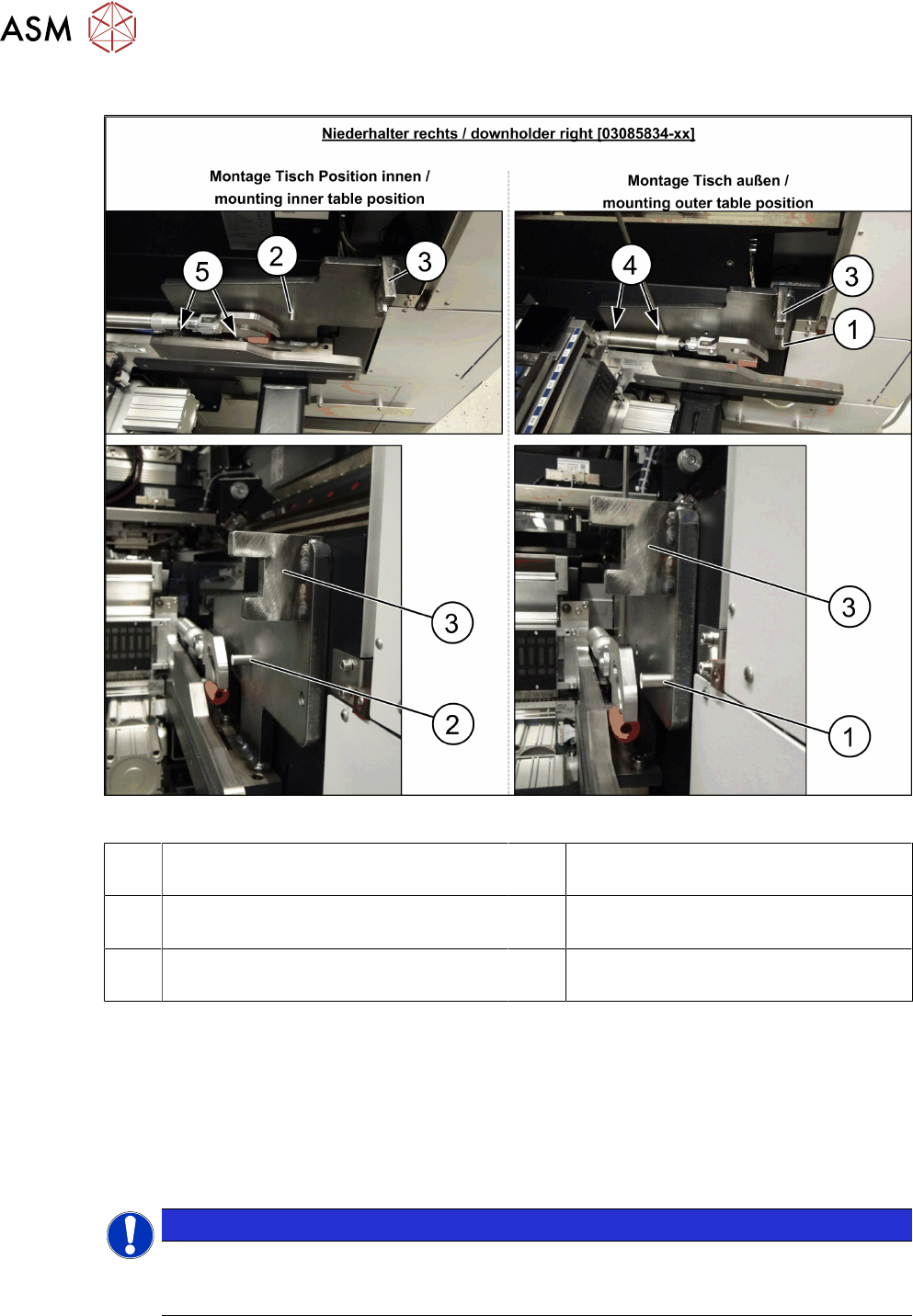
Fitting the right downholder
Fig.35: Downholder
1 Pin DIN6325-10-M6x30-St [00358814-
xx] at position inside
2 Pin DIN6325-10-M6x30-St [00358814-
xx] at position outside
3 Docking aid 4 Screw ISO4762-M8x40-A2-70
[03042589-xx]
5 Screw ISO4762-M8x40-A2-70
[03042589-xx]
► Remove the two screws(4) and(5) on the right side of the COT insert. The screws are under-
neath the COT insert cylinder.
► Place the "downholder COT-i right assembly" [03085834-xx] on the right side of the COT in-
sert so that the holes are aligned with one another.
► Screw the downholder tight with the two new screws(4) and(5).
► The downholder pin(2) must always be approx. 10mm before the claws of the insert and the
docking aid(3)
, behind the machine protection (cover flap).
NOTICE
Screws
Insert the new screws into the holes in the downholder and position the downholder to-
gether with the screws onto the COT insert.
4 Appendix
4.1 Excerpts from the Service Manual
Assembly Instructions / Montageanleitung SIPLACE SX1/SX2 V3 Stationäre Kamera Typ 25/33 (GigE) Stationary
Camera Type 25/33 (GigE) 03/2021
87
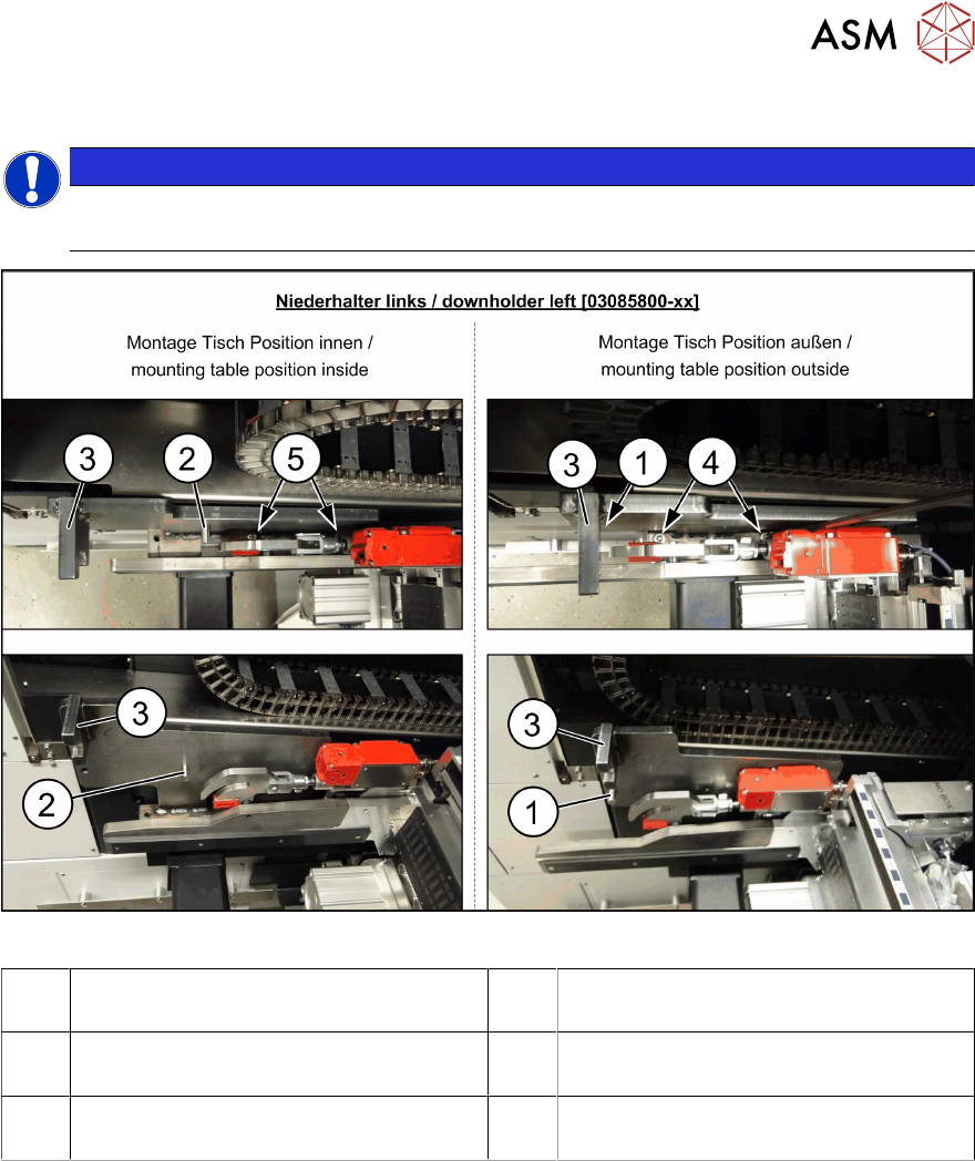
Fitting the left downholder
NOTICE
COT-I30 insert for the WPC
When using a COT-I30 insert for the WPC, you only need to fit the downholder on the right.
Fig.36: Downholder
1 Pin DIN6325-10-M6x30-St [00358814-
xx] at position inside
2 Pin DIN6325-10-M6x30-St [00358814-
xx] at position outside
3 Docking aid 4 Screw ISO4762-M8x40-A2-70
[03042589-xx]
5 Screw ISO4762-M8x40-A2-70
[03042589-xx]
► Remove the two screws(4) and(5) on the left side of the COT insert.
► Place the "downholder COT-i left assembly" [03085800-xx] on the left side of the COT insert
so that the holes are aligned with one another.
► Screw the downholder tight with the two new screws(4) and(5).
► The downholder pin(2) must always be approx. 10mm before the claws of the insert and the
docking aid(3)
, behind the machine protection (cover flap).
4 Appendix
4.1 Excerpts from the Service Manual
88 Assembly Instructions / Montageanleitung SIPLACE SX1/SX2 V3 Stationäre Kamera Typ 25/33 (GigE) Stationary
Camera Type 25/33 (GigE) 03/2021
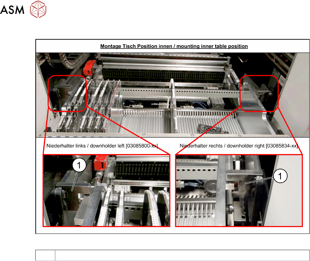
Checking the downholder positions
Fig.37: Table position
1 Docking aid
► Move the component trolley back into the machine.
► The component trolley height must be adjusted so that the side rails fit into the recess on the
docking aid(1)
. (See also Setting the Changeover Table Height)