00198706-01_AI_Stationaere_Kamera_25_33_GigE_SXV3_DE_EN.pdf - 第85页
4 Appendix 4.1 Excerpts from the Service Manual Assembly Instructions / Montageanleitung SIPLACE SX1/SX2 V3 Stationäre Kamera Typ 25/33 (GigE) Stationary Camera Type 25/33 (GigE) 03/2021 85 Fig.34: Docking aid 1 Pin DIN…
4 Appendix
4.1 Excerpts from the Service Manual
84 Assembly Instructions / Montageanleitung SIPLACE SX1/SX2 V3 Stationäre Kamera Typ 25/33 (GigE) Stationary
Camera Type 25/33 (GigE) 03/2021
4.1.2.1 Fitting the Downholder
Preparing the downholder
NOTICE
Only when table position changed
The downholder pin only needs to the converted if the table position inside/outside has
been changed.
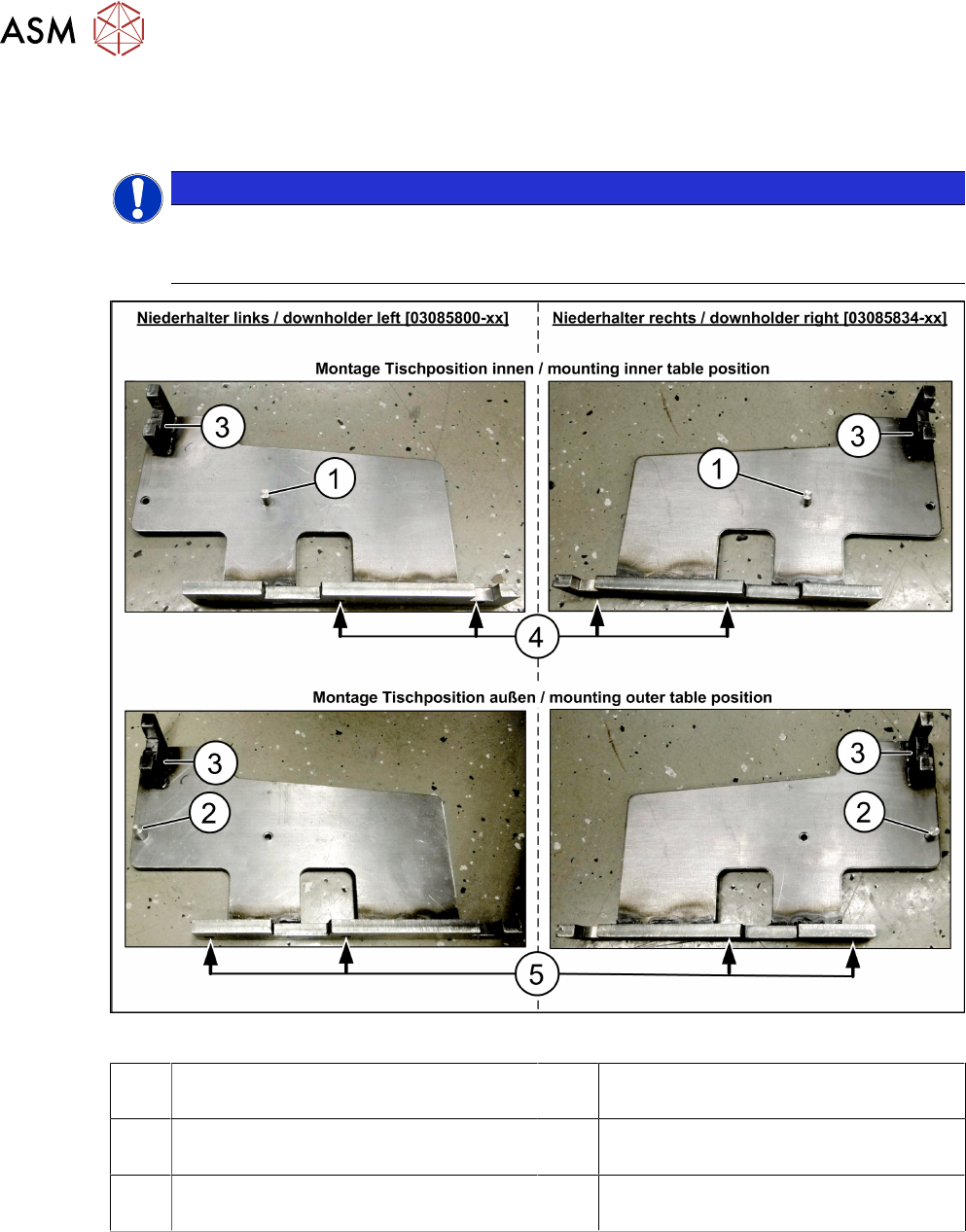
Fig.33: Downholder
1 Pin DIN6325-10-M6x30-St [00358814-
xx] at position inside
2 Pin DIN6325-10-M6x30-St [00358814-
xx] at position outside
3 Docking aid 4 Screw ISO4762-M8x40-A2-70
[03042589-xx]
5 Screw ISO4762-M8x40-A2-70
[03042589-xx]
Depending on the position of the component trolley (inside/outside), the downholder pin
[03085247-xx] is fitted either in position(1)
or(2). This is then secured in place with a screw
ISO4762-M6x12-A2-70 [03042572‑xx].
After installation, the docking aid (3) docking aid on the downholder is always in the same position
as the docking unit that was previously dismantled (near the protective cover). The downholder pin
and therefore the assembly position of the downholder depends on the table position (inside/out-
side).
4 Appendix
4.1 Excerpts from the Service Manual
Assembly Instructions / Montageanleitung SIPLACE SX1/SX2 V3 Stationäre Kamera Typ 25/33 (GigE) Stationary
Camera Type 25/33 (GigE) 03/2021
85
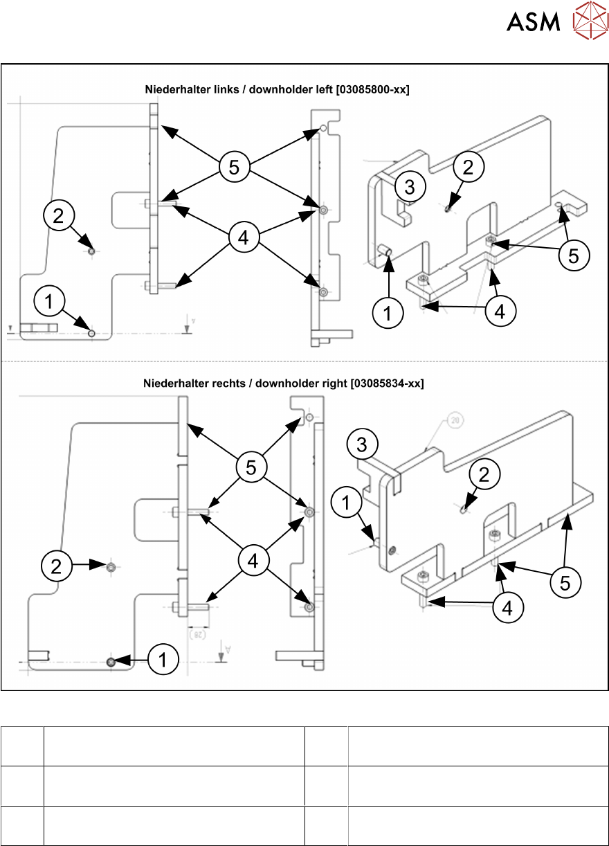
Fig.34: Docking aid
1 Pin DIN6325-10-M6x30-St [00358814-
xx] at position inside
2 Pin DIN6325-10-M6x30-St [00358814-
xx] at position outside
3 Docking aid 4 Screw ISO4762-M8x40-A2-70
[03042589-xx]
5 Screw ISO4762-M8x40-A2-70
[03042589-xx]
The position of the fastening screws(4) and(5) depends on the position of the COT insert.
When the table is in the inner position, the downholder pin(1) is moved approx. 125mm inwards,
towards the docking aid(3)
and the downholders are fixed with two new screws each to the posi-
tion(4)
, together with the COT insert.
When the table is in the outer position, the downholder pin(2) is underneath the docking aid(3)
and the downholders are fixed with two new screws each to the position(5), together with the COT
insert.
4 Appendix
4.1 Excerpts from the Service Manual
86 Assembly Instructions / Montageanleitung SIPLACE SX1/SX2 V3 Stationäre Kamera Typ 25/33 (GigE) Stationary
Camera Type 25/33 (GigE) 03/2021
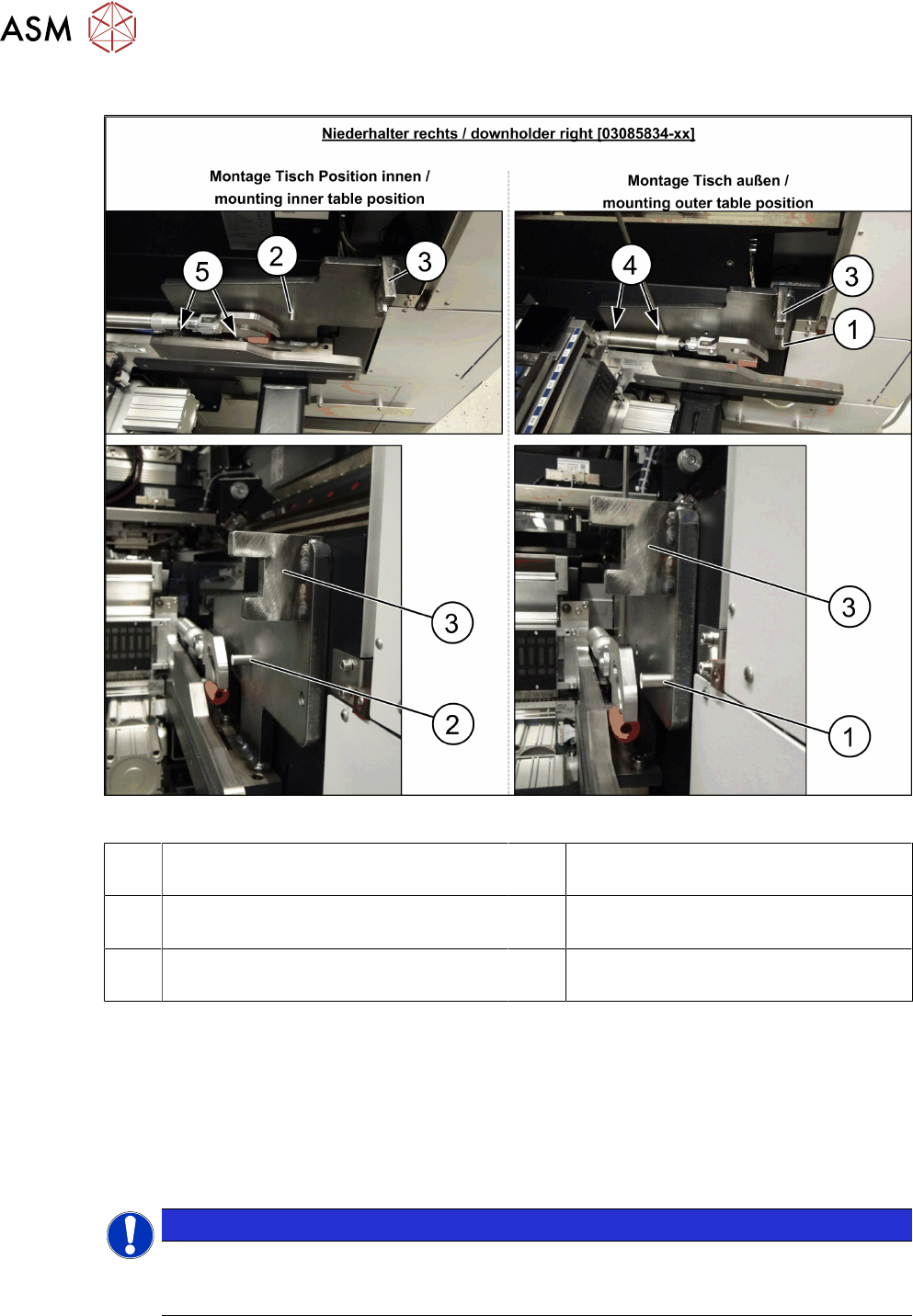
Fitting the right downholder
Fig.35: Downholder
1 Pin DIN6325-10-M6x30-St [00358814-
xx] at position inside
2 Pin DIN6325-10-M6x30-St [00358814-
xx] at position outside
3 Docking aid 4 Screw ISO4762-M8x40-A2-70
[03042589-xx]
5 Screw ISO4762-M8x40-A2-70
[03042589-xx]
► Remove the two screws(4) and(5) on the right side of the COT insert. The screws are under-
neath the COT insert cylinder.
► Place the "downholder COT-i right assembly" [03085834-xx] on the right side of the COT in-
sert so that the holes are aligned with one another.
► Screw the downholder tight with the two new screws(4) and(5).
► The downholder pin(2) must always be approx. 10mm before the claws of the insert and the
docking aid(3)
, behind the machine protection (cover flap).
NOTICE
Screws
Insert the new screws into the holes in the downholder and position the downholder to-
gether with the screws onto the COT insert.