00198706-01_AI_Stationaere_Kamera_25_33_GigE_SXV3_DE_EN.pdf - 第77页
3 Installation 3.7 Fitting the reject bin (FC camera only) Assembly Instructions / Montageanleitung SIPLACE SX1/SX2 V3 Stationäre Kamera Typ 25/33 (GigE) Stationary Camera Type 25/33 (GigE) 03/2021 77 3.7 Fitting the rej…
3 Installation
3.6 Electrical connections
76 Assembly Instructions / Montageanleitung SIPLACE SX1/SX2 V3 Stationäre Kamera Typ 25/33 (GigE) Stationary
Camera Type 25/33 (GigE) 03/2021
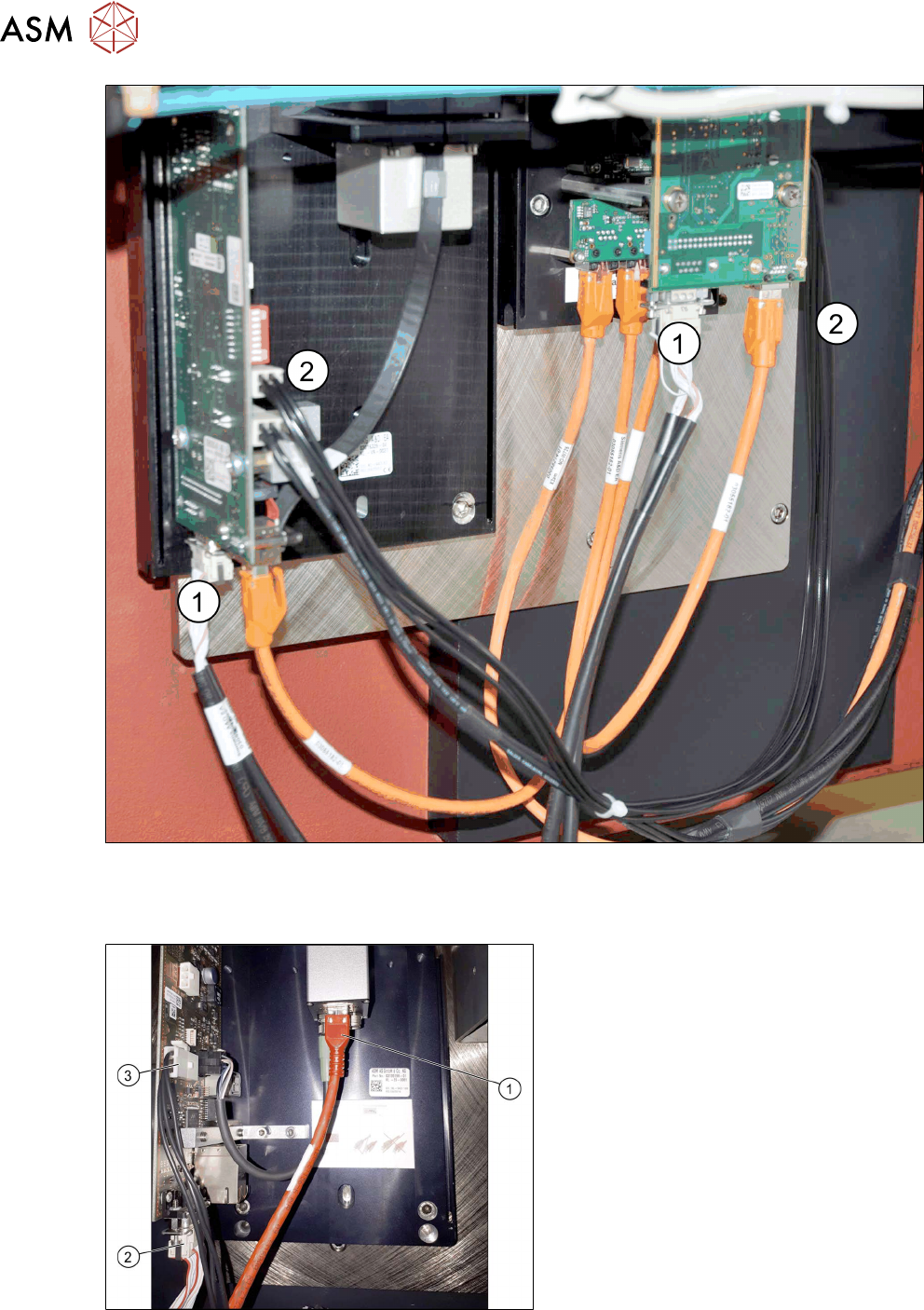
Fig.21: Cables for IC and FC camera
► Connect the CAN cable(1) leading from the machine to the camera CAN connections.
► Connect the power supply cable(2) to the FC camera (X4) and the IC camera (X4 or X5).
Fig.22: Connecting the IC camera
► Connect the camera cable (1), the CAN
bus cable (2)
and the power supply
cable (3)
to the stationary camera, ac-
cording to the respective camera con-
figuration.
3 Installation
3.7 Fitting the reject bin (FC camera only)
Assembly Instructions / Montageanleitung SIPLACE SX1/SX2 V3 Stationäre Kamera Typ 25/33 (GigE) Stationary
Camera Type 25/33 (GigE) 03/2021
77
3.7 Fitting the reject bin (FC camera only)
When using the "stationary camera for CPP head" option, you need to fit an additional reject bin for
components >36x36mm. This is identical to the Twin reject bin.
This reject bin is included in the delivery packages for the stationary camera and the HRK for
SIPLACE Twin.
Parts
Quantity Designation Item no.
1 Holder for reject bin P001 03063283-xx
2 ISO 4762 - M 6 x 10-A2-70 03042571-xx
1 Reject bin assembly 03072806-xx
You also need the "Verify component reject bin, SX1/2" [00519848‑xx].
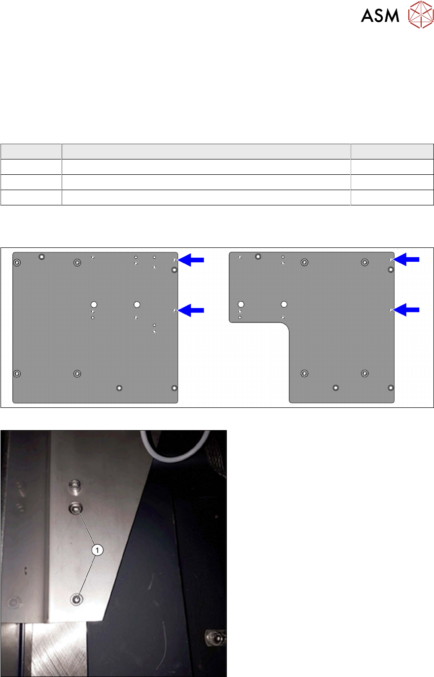
Fitting the holder
Fig.23: Reject bin screw points on the support plate assemblies
Fig.24: Holder (example of location 2 shown)
► Use the two fastening screws (1)
(M6x10) to fit the holder to the support
plate assembly.
3 Installation
3.7 Fitting the reject bin (FC camera only)
78 Assembly Instructions / Montageanleitung SIPLACE SX1/SX2 V3 Stationäre Kamera Typ 25/33 (GigE) Stationary
Camera Type 25/33 (GigE) 03/2021
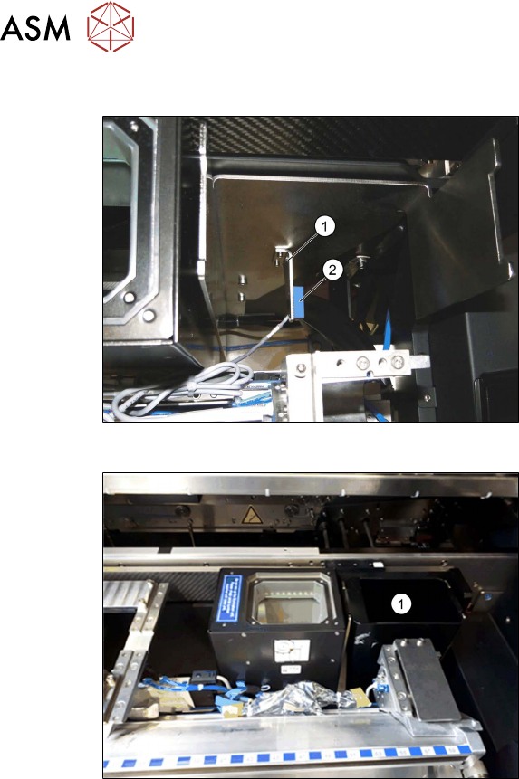
Fitting the sensor
Fig.25: Reject bin sensor
► Fit the holder(1) for the sensor, sup-
plied with the "Verify component reject
bin, SX1/2" [00519848‑xx], and fix with
two screws.
► Fit the sensor. This is located on the
COT insert.
See also the assembly instructions for
the "Verify component reject bin SX1/
SX2, DE+EN" [00196615‑xx]
Fig.26: Reject bin
► Insert the reject bin(1).