00198706-01_AI_Stationaere_Kamera_25_33_GigE_SXV3_DE_EN.pdf - 第70页
3 Installation 3.4 Preparatory work on the cameras 70 Assembly Instructions / Montageanleitung SIPLACE SX1/SX2 V3 Stationäre Kamera Typ 25/33 (GigE) Stationary Camera Type 25/33 (GigE) 03/2021 Setting the camera ► Set th…
3 Installation
3.4 Preparatory work on the cameras
Assembly Instructions / Montageanleitung SIPLACE SX1/SX2 V3 Stationäre Kamera Typ 25/33 (GigE) Stationary
Camera Type 25/33 (GigE) 03/2021
69
3.4 Preparatory work on the cameras
NOTICE
The following tasks are principally the same for both camera types. Any relevant differ-
ences will be mentioned explicitly.
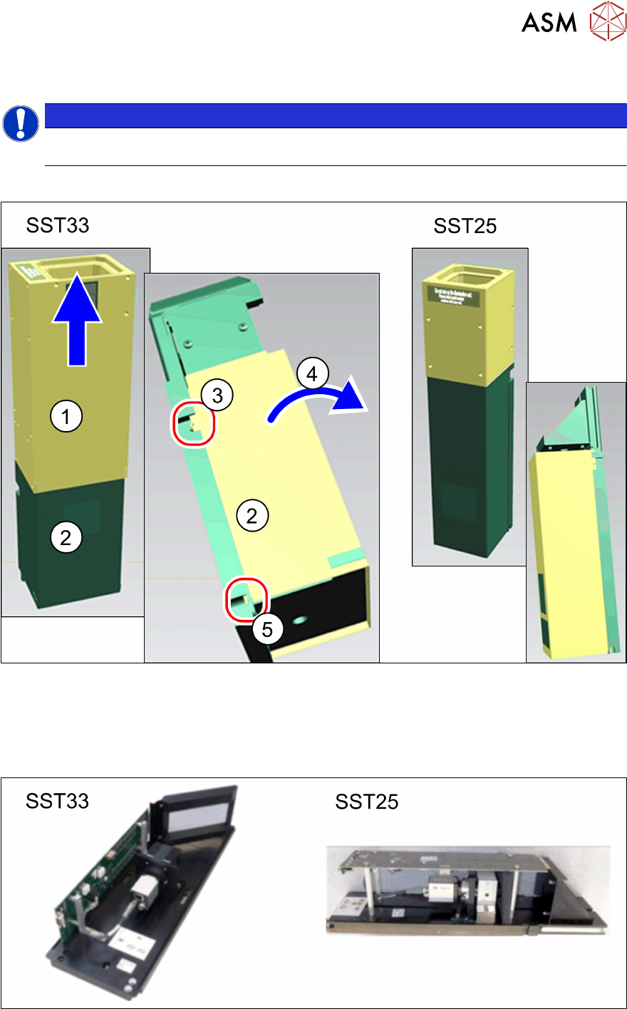
Removing the upper section and cover
Fig.9: Removing the upper section and bottom cover
► Pull the top section(1) straight up and off the bottom section.
► Press the bottom cover(2) out of the pins on the left and right(3) and swing the cover for-
wards(4)
.
► Lift the cover slightly(5) and take off.
Fig.10: Camera lower parts for IC camera (SST33) and FC camera (SST25)

3 Installation
3.4 Preparatory work on the cameras
70 Assembly Instructions / Montageanleitung SIPLACE SX1/SX2 V3 Stationäre Kamera Typ 25/33 (GigE) Stationary
Camera Type 25/33 (GigE) 03/2021
Setting the camera
► Set the DIP switch S1 as follows:
DIP switch S1 for SST25 and SST33:
Switch Status Signal name Description
S1.1 OFF VCU_CODE OFF: normal operation
ON: Reset
Location 1 Location 2 Location 3 Location 4
S1.2 ON/OFF *) PORTAL_ID_0 OFF ON OFF ON
S1.3 ON/OFF *) GANTRY_ID_1 OFF OFF ON ON
S1.4 OFF SMD_LED OFF: standard LED
ON: SMD LED
S1.5 OFF CAN_H OFF: with CAN terminator
ON: without CAN terminator
S1.6 ON/OFF CAN_GROUP OFF: FC camera
ON: IC camera
*) Set the location at which the stationary camera is fitted. There are no locations 3 or 4 on the
SIPLACE SX1/SX2.
See also
2 4.2.1 "PCBs Stationary Cameras" [}90]
3 Installation
3.5 Fitting the cameras
Assembly Instructions / Montageanleitung SIPLACE SX1/SX2 V3 Stationäre Kamera Typ 25/33 (GigE) Stationary
Camera Type 25/33 (GigE) 03/2021
71
3.5 Fitting the cameras
3.5.1 Fitting the support plate assembly
The IC camera is necessary for fitting the FC camera or a 3D coplan module. Both mounting plates
(for location 1 and 2) are therefore provided in the IC retrofit kit.
If it has not already been fitted, fit the support plate assembly next. The cameras and reject bin are
then installed on the support plate assembly.
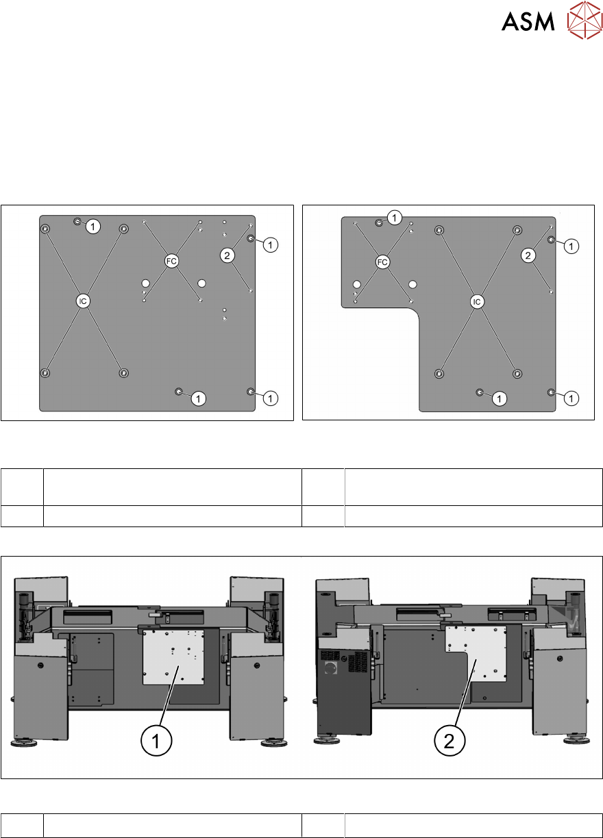
Fig.11: Support plate assembly location 1
[03070836‑xx]
Fig.12: Support plate assembly location 2
[03070862‑xx]
1 Fixture points for support plate assembly
on the machine frame
2 Fixture points for reject bin
FC Fixture points for FC camera (type 25) IC Fixture points for IC camera (type 33)
Fig.13: Support plate assemblies on machine bottom section
1 Support plate assembly on location 1 2 Support plate assembly on location 2
► Fit and fix the support plate assembly with four screws (ISO4762-M6x22-A2-70).